Sign In
Upload
Manuals
Brands
Hobart Manuals
Portable Generator
120CU20
Hobart 120CU20 Manuals
Manuals and User Guides for Hobart 120CU20. We have
1
Hobart 120CU20 manual available for free PDF download: Operation And Maintenance Manual With Illustrated Parts List
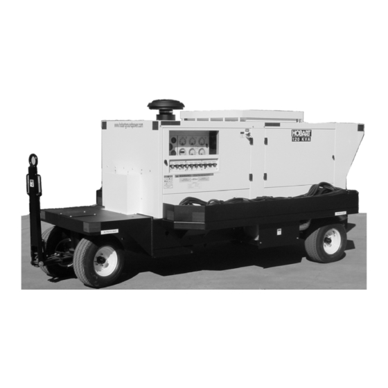
Hobart 120CU20 Operation And Maintenance Manual With Illustrated Parts List (247 pages)
120 kVA, 3 Phase, 115/200 Volt, 400 Hz. Generator Set Series 500120
Brand:
Hobart
| Category:
Portable Generator
| Size: 9 MB
Table of Contents
Illustrated Parts List
1
General
7
Installation and Grounding of Electrically Powered Equipment
7
Safety Warnings and Cautions
7
Shock Prevention
7
Electrical Short Circuits and Overloads
8
Fire and Explosion Prevention
8
Output Cables and Terminals
8
Service and Maintenance
8
Bodily Injury Prevention
9
Equipment Precautionary Labels
9
Medical and First Aid Treatment
9
Toxic Fume Prevention
9
Introduction
11
Table of Contents
13
Wet Stacking
16
Chapter 1 Description/Operation
17
General
17
Optional Equipment
17
Optional Equipment - Appendix A
17
Orientation
17
Section 1 Description
17
Canopy
18
Engine Electronic Control Module
18
Protective Monitoring
18
Special Features
18
Voltage Regulator
18
AC Generator Protective System Specifications
19
AC Generator Specifications
19
Physical Specifications
19
DC Output Specifications
20
DC Protective System Specifications
20
Engine Specifications
20
Basic Engine
21
Engine and Generator
21
Engine Manufacturer’s Equipment
21
Normal Operating Characteristics
21
Coolant High Temperature Shutdown System
22
Emergency Shutdown/Reset Switch (S28)
22
Engine-Cooling Fan
22
Factory Installed Equipment
22
Engine Faults
23
General Assembly of Generator Set
24
Main Components of Generator Set (Right Side)
25
Main Components of Generator Set (Left Side)
26
Air Cleaner and Service Indicator
27
Control Box Assembly
27
Generator
27
Operator Controls
27
Engine Hour Meter (M4)
29
Engine Oil Pressure Gauge (M24)
29
Engine on Indicating Light (DS58)
29
Panel Lights and Panel Light Push-Button Switch
29
Engine Fuel Gauge
30
Engine Voltmeter
30
Fault Code Meter and “TEST/RESET” Push-Button Switch
30
“ENGINE STOP” Push-Button Switch
30
DC Generator Output Monitors (Meters)
31
Front LED Display
31
“DC OUTPUT” Contactor Switch
31
“STARTING CURRENT” Switch
31
Control Box Interior Components
32
EF Bypass Switches
32
Circuit Breakers (CB1, CB4, CB7)
33
Digital Control PC Board
33
Digital Control PC Board [CTL] (A3)
33
Regulated-Diagnostic Switch
33
Engine Interface PC Board
34
Engine Specific PC Board
34
Voltage Regulator PC Board
35
+5, -12 VDC Power Source
36
Transformer-Rectifier PC Board
36
Control System Power Source
37
Current Transformers
38
Line-Drop Compensation
38
Load Contactor
38
Power Module Panel Assembly
38
Output Power Module Components
39
Cold Weather Starting System (BH1)
40
Intake Air Heater
40
Heat Sink / Diode Assembly
41
Input Contactor
41
Transformer Assembly (T401)
41
Transformer-Rectifier Assembly Components
41
Transformer-Rectifier Components
42
Engine Coolant
43
Engine Oil and Coolant Capacities
43
Preparation For: Use, Storage, or Shipping
43
Check Batteries
44
Engine Lubricating Oil Level
44
Installing Three-Phase AC Output Cables
44
Oil Fill and Oil Level Check Locations
44
Installing the DC Output Cable
45
Lower Panel Assembly
46
Output Cable Connection
46
Long Time Storage
47
Preparation for Storage
47
Temporary Storage
47
Preparation for Shipment
48
400 Hz. Operating Procedure
49
General
49
Pre-Start Inspection
49
Section 3 Operation
49
Normal Engine Starting Procedures
51
Failed Starting Procedure
52
Power Delivery
52
Discontinue Power Delivery with Unit Shutdown
53
Emergency Conditions
53
Failed Power Delivery
53
Normal Conditions
53
DC Operating Procedure
54
Discontinue Power Delivery
54
Normal Power Delivery
54
Simultaneous AC and DC Operation
54
Chapter 2 Servicing / Troubleshooting
55
General
55
Identification of Interval Periods
55
Maintenance Inspection/Check
55
Maintenance Schedule
55
Service and Troubleshooting
55
Inspection/Check
57
Electrical (400 Hz System) -- Check Output Voltage
58
Engine
58
Change Air Cleaner Cartridge
58
Electrical System (12 VDC) – Check Battery Terminals
58
“AR” Checks and Operations
58
Check Coolant Level
59
Check Crankcase Oil Level
59
Check for Leaks and Correct
59
Drain Fuel Lubricity Filter/Pre-Filter Element
59
“A” Checks and Operations (10 Hours or Daily)
59
Check All Lights
60
Check Exhaust System
60
Check Fault Code Meter
60
Electrical System (12 VDC)
60
Charge-Air-Cooler (CAC) and Piping
61
Check Fuel Pump
61
Check Radiator Core and Hoses
61
Electrical (400 Hz System)
61
“B” Check and Operations (250 Hours or 3 Months)
61
Check Coolant Additive Concentration
62
Check Engine and Generator Mounts
62
Electrical (12 VDC System)
62
Inspect Wiring and Connections
62
Protective Monitoring Circuits
62
“C” Checks and Operations (500 Hours or 6 Months).
62
Check And/Or Adjust Valve Clearance
63
Check Belts Conditions and Tensioner
63
Check Fan Hub and Drive Pulley
63
Check Hose Clamps on Air Intake Side
63
Check Water Pump
63
Steam Clean Engine
63
Check Alternator and Cranking Motor
64
Clean Fuel System
64
Engine Accessories
64
Check Vibration Damper
65
Lamps Circuit Breakers, and Fuses
65
Seasonal Maintenance Checks Spring/Fall (Engine)
65
“F” Checks and Operations (2000 Hours or 2 Years).
65
Circuit Breaker Identification Chart
66
Fuse Identification Chart
66
Lamp Identification Chart
66
AC Generator
67
General
67
Lubrication Schedule
67
Maintenance Procedures
67
Changing Engine Oil
68
Oil Specification
68
Oil Viscosity
68
Lubricants Chart
70
Lubrication System
70
Alternator
71
Engine Accessories Lubrication
71
Starter
71
Water Pump
71
Air Filter Element Replacement Part Number
72
Changing the Air Filter
72
Inspecting the Air Cleaner
72
Servicing the Air Cleaner
72
Cold Weather Operation
73
Engine Fuel System
73
How to Select Fuel—Quality
73
Draining the Fuel Water Separator Bowl
74
Fuel Pump
74
Fuel Water Separator
74
Priming Fuel Water Separator
74
Changing the Lubricity Fuel Filter
75
Fuel/Water Separator/Lubricity Fuel Filter
75
Engine Cooling System
76
Fuel Return
76
Priming Fuel System (When Applicable)
76
Coolant
77
Radiator Cap
77
Checking Antifreeze Solution
78
Draining the Cooling System
78
Flushing the Cooling System
78
Selecting Antifreeze
78
Filling the Cooling System
79
Thermostat
79
To Add Coolant
79
Checking Belt Tension
80
Drive Belt
80
Generator Maintenance
80
Adjustment/Test
81
General
81
Pre-Operational Test Procedures
81
Testing the 400 Hz. Generator Set
81
Check Adjustable Voltage Range
83
Operational Test Procedures
83
Testing the No. 1 Output Circuit
85
EF Bypass Indication
86
Check Accuracy of AC Ammeter
87
Check Accuracy of AC Voltmeter
87
Check Operation of the “METER SELECT” Switch
87
Testing the No. 2 Output Circuit
87
Check Accuracy of Frequency Meter
88
Check Operation of Under-Voltage Circuit and Fault Code Display
88
Check Under-Frequency Circuit and Fault Code Display
89
Check Over-Frequency Circuit and Fault Code Display
90
Testing for Engine ECM Faults
90
Generator Set Adjustment
92
Re-Checking the Entire Unit after Testing
92
Voltage Regulator Adjustment
92
Adjust Voltage Control
93
Output Voltage Adjustment
93
Adjust Line-Drop Compensation
94
Basic Engine Adjustments
94
Test the Voltage Regulator
94
Engine Accessories Adjustment
95
Generator and Exciter Test
95
Generator and Exciter Test Readings
95
Generator Connections
95
Diode Test
96
Testing the Transformer-Rectifier
96
Current Limiting / Soft Starting Control
97
Over-Voltage Protection
97
Overload Protection
97
Under-Voltage Protection
97
Adjusting the Transformer-Rectifier
98
Control Interlock Kit
98
Silicon Diodes
98
Temperature Overload Protection
98
Equipment for Troubleshooting
99
General
99
Parts Replacement
99
Troubleshooting Procedures
99
400 Hz. Test Values
100
Check Connections and Leads
100
Connection and Schematic Diagrams
100
Engine Troubleshooting
100
Illustrations
100
Commands
101
Engine Start Mode
101
GPU Control Monitoring
101
Self-Test Mode
101
Engine Idle Mode
102
Engine Run Mode
102
Engine Shutdown Mode
102
Engine Stop Mode
102
Fault Code Display
103
Idle Mode
103
Run Mode
103
Stop Mode
103
Extracting Fault Code Information
104
Fault Meter Display
104
Operation Monitoring
104
Engine Controls
108
Generator Excitation Circuits
111
Load Contactor Operating Circuits
112
Protective Circuit
114
Generator
116
T-R Controls and Components
117
GPU Commands
119
Troubleshooting Table
119
Faults
120
Chapter 3 Overhaul / Major Repair
123
Conditions for Exciter Removal
125
Exciter Armature Replacement
125
Preparation for Exciter Armature Removal
125
Tools Needed for Exciter Armature Removal and Installation
125
Exciter Armature Removal
126
Removing the Exciter Armature
126
Removing the Threaded Key with Sling-Hammer Puller
126
Sling Hammer Puller
127
Exciter Armature Installation
128
Preparation for Exciter Armature Installation
128
Install the Machine Key
130
Recommended Products Manufacturers
130
Coupling Assembly
131
Disassembly
131
Exciter Armature
123
General Assembly
123
Dual Bearing Flexible Coupling
131
General
131
Separate Engine and Generator
131
Access to Coupling Bolts
132
Remove Coupling Assembly
132
Hub and Bushing
133
Bushing Kit
134
Bushing Replacement
134
Coupling Service
134
Replacement Coupling Kit
134
Coupling Installation
135
Reassemble Engine and Generator
136
Run-In and Periodic Check
137
Bushing Installation
138
Assembly Procedure
139
Measure from Mounting Face to Adapter Ring
139
Measuring from Mounting Face to Bushing
140
Generator Assembly Removal
141
Generator Lifting Arrangement
142
Removing the Generator Assembly
142
Component Removal Required for Access to Generator
143
Generator Assembly Installation
144
Remounting the Generator Assembly
144
Remounting the Previously Removed Assemblies
144
Arrangement
145
Chapter 4 Illustrated Parts List
145
Explanation of Parts List
145
General
145
Illustrated Parts List
145
Introduction
145
Manufacture's Codes
145
Parts List Form
145
Purpose
145
Section 1 Introduction
145
FACTORY PART NUMBER Column
146
NOMENCLATURE Column
146
UNITS PER ASSEMBLY Column
146
Explanation of Manufacturer’s (Vendor) Code List
147
Explanation of Parts List Arrangement
151
Symbols and Abbreviations
151
Labels and Reflectors
154
Frame Assembly
156
Canopy Assembly
158
Canopy Doors
160
Internal Components
162
Door Control Panel Assembly
164
All Other Push-Buttons
168
Lamps and Meter Select Pushbuttons
168
400 Hz. Power Module Assembly
170
Cooling System Components
172
Engine Ground Plate and Cables
174
120CU20 / Series 500120 / 400 Hz. Generator Set
175
Fuel System Components
176
Engine Exhaust Components
178
VDC Battery System
180
Air Cleaner Components
182
Engine Components
184
Engine Electrical Panel Components
186
Transformer-Rectifier Assembly (DC Option)
190
DC Output Contactor (DC Option)
192
T-R Interlock Kit (DC Option Accessory)
194
Explanation of Numerical Index
197
Numerical Index
197
Analog Meter Connections for TR Meters
211
Digital Meter Connections for TR Meters
211
Legend
221
Option/Features Available
239
Options / Features
239
Diesel Engines
241
Wet-Stacking in Generator Set
241
Unusual Service Conditions
243
Filter Part Numbers
245
Generator Model Number
245
Preventive Maintenance
245
Filter Kits
246
Hobart Ground Power - Supply Contact Information
246
Advertisement
Advertisement
Related Products
Hobart 140GT17P
Hobart 140GT17K
Hobart 140GT17P5
Hobart 100D20
Hobart 100D20P5
Hobart Handler 125
Hobart Handler 125 EZ
Hobart CHAMPION 10,000
Hobart Champion 145
Hobart 1776
Hobart Categories
Welding System
Dishwasher
Mixer
Kitchen Appliances
Inverter
More Hobart Manuals
Login
Sign In
OR
Sign in with Facebook
Sign in with Google
Upload manual
Upload from disk
Upload from URL