Table of Contents
Advertisement
Quick Links
OPERATION AND MAINTENANCE
SOLID STATE TRANSFORMER-RECTIFIER
SPECIFICATION
S6883-1
S6883-2
S6883A-1
S6883A-2
S6883A-3
MANUAL
GPU-600
RATED OUTPUT: 28 V-DC, 600 A
INPUT VOLTAGE
208/230/460 V, 3-PHASE 60-Hz
220/380 V, 3-PHASE
208/230/460 V, 3-PHASE 60-Hz
220/380 V, 3-PHASE
230/460/575 V, 3-PHASE 60-Hz
HOBART BROTHERS COMPANY
POWER SYSTEMS GROUP
GROUND POWER EQUIPMENT
TROY, OHIO 45373
with
for
FREQUENCY
50-Hz
50-Hz
Manufactured by
U.S.A.
OM-2010
121585
Revised 121691
031893
MODEL NUMBER
6T28-600CL
5T28-600CL
6T28-600CL
5T28-600CL
6T28-600CL
Advertisement
Table of Contents
Troubleshooting

Related Manuals for Hobart GPU-600


Summary of Contents for Hobart GPU-600
- Page 1 6T28-600CL S6883-2 220/380 V, 3-PHASE 50-Hz 5T28-600CL S6883A-1 208/230/460 V, 3-PHASE 60-Hz 6T28-600CL S6883A-2 220/380 V, 3-PHASE 50-Hz 5T28-600CL S6883A-3 230/460/575 V, 3-PHASE 60-Hz 6T28-600CL Manufactured by HOBART BROTHERS COMPANY POWER SYSTEMS GROUP GROUND POWER EQUIPMENT TROY, OHIO 45373 U.S.A.
- Page 2 This page intentionally left blank...
- Page 3 SAFETY INSTRUCTIONS AND WARNINGS FOR ELECTRICAL POWER EQUIPMENT WARNING ELECTRIC SHOCK can KILL. Do not touch live electrical parts. ELECTRIC ARC FLASH can injure eyes, burn skin, cause equipment damage, and ignite combustible material. DO NOT use power cables to break load and prevent tools from causing short circuits. IMPROPER PHASE CONNECTION, PARALLELING, OR USE can damage this and attached equipment.
- Page 4 C . FIRE AND EXPLOSION PREVENTION Fire and explosion are caused by electrical short circuits, combustible material near engine exhaust pip- ing, misuse of batteries and fuel, or unsafe operating or fueling conditions. 1. Electrical Short Circuits and Overloads Overloaded or shorted equipment can become hot enough to cause fires by self destruction or by causing nearby combustibles to ignite.
- Page 5 OM-2010 Table of Contents SUBJECT CHAPTER/SECTION PAGE WARNING LIST OF EFFECTIVE PAGES INTRODUCTION CHAPTER 1. RECEIPT OF EQUIPMENT AND INSTALLATION SECTION 1. RECEIPT OF EQUIPMENT SECTION 2. INSTALLATION A. Location B. Internal Wiring check C. Connecting the Machine to Line Voltage D.
- Page 6 OM-2010 SUBJECT CHAPTER/SECTION PAGE (1) Electronic Overvoltage/Overload Trip Circuit 2-1 (2) Electronically Controlled Current Limit (3) Regulated DC Output Voltage (4) Thermal Overload Trip SECTION 2. OPERATION 1. General 2. Preparation for Operation 3. Operation Procedure A. Input Control Functions B.
- Page 7 2. Purpose 3. Arrangement 4. Explanation of Parts List A. Contents B. Parts List Form (1) “FIGURE-ITEM NO.” Column (2) “HOBART PART NUMBER” Column (3) “NOMENCLATURE” Column (4) “EFF” (Effective) Column (5) “UNITS PER ASSEMBLY” Column SECTION 2. MANUFACTURER’S CODES 1.
- Page 8 OM-2010 SUBJECT CHAPTER/SECTION PAGE SECTION 3. PARTS LIST 1. Explanation of Parts List Arrangement 2. Symbols and abbreviations SECTION 4. NUMERICAL INDEX 1. Explanation of Numerical Index CHAPTER 5. OPTIONAL EQUIPMENT CHAPTER 6. MANUFACTURER’S LITERATURE UNUSUAL SERVICE CONDITIONS Table of Contents April 10/89 Revised Page 4...
- Page 9 OM-2010 LIST OF EFFECTIVE PAGES CHAPTER/ CHAPTER/ SECTION PAGE DATE SECTION PAGE DATE List of Apr 10/89 Effective Apr 10/89 Pages Apr 10/89 Apr 10/89 Apr 10/89 Introduction Apr 10/89 Apr 10/89 Introduction Apr 10/89 Introduction Apr 10/89 Apr 10/89 Introduction Apr 10/89 Apr 10/89...
- Page 10 OM-2010 LIST OF EFFECTIVE PAGES CHAPTER/ SECTION PAGE DATE Apr 10/89 Apr 10/89 Apr 10/89 Apr 10/89 Apr 10/89 Apr 10/89 List of Effective Pages April 10/89 Revised Page 2...
- Page 11 OM-2010 INTRODUCTION 1. General This Introduction is intended to give the reader a better understanding of how to use the manual properly. The manual can be very helpful to you if you will READ THIS INTRODUCTION FIRST. READ AND UN- DERSTAND THE MANUAL BEFORE ATTEMPTING TO OPERATE, INSTALL, OR REPAIR THIS EQUIPMENT.
- Page 12 OM-2010 5. Format A. Paragraphing and Outlining The material within each Section is divided into main subjects with applicable paragraph headings and sub-headings as required. This method not only helps keep information closely knit, but provides a means of identifying material for reference purposes. For example, a portion of the Description Sec- tion might logically follow this arrangement and paragraphing: 1.
- Page 13 OM-2010 (2) List of Illustrations A complete list of Illustrations follows the Table of Contents and includes the title, figure number, and Chapter/Section, with page number location of all illustrations contained in the manual. Lo- cate the appropriate title in the List of Illustrations, then turn to the Chapter/Section and page number indicated.
- Page 14 A special connector for the two output leads and the ground lead may be required when delivering power directly to an aircraft. 7. SERVICE If you have any questions concerning your Hobart Power Systems Division equipment, please contact our Service Department by mail, telephone or FAX. Write:...
- Page 15 (railroad, trucking company, etc.) at once and file a claim for damages. If you require assistance with a damage claim, furnish Hobart Brothers Company with full information about the claim. If the shipment is in error, contact Order Department, Hobart Brothers Company, Power Systems Division, Troy, Ohio 45373.
- Page 16 OM-2010 installation Dimension Drawing Figure 1 April 10/89 Revised Page 2...
- Page 17 OM-2010 SECTION 2. INSTALLATION A. Location For best operating characteristics and longest unit life, select an installation site that is not exposed to high humidity, dust, high ambient temperature, flooding, or corrosive agents. Moisture can condense on electrical components, causing corrosion or shorting of circuits. Dirt on components helps retain this mois- ture in addition to providing a conducting material.
- Page 18 NOTE: After connecting the input cables, it is recommended that Hobart #904021 urethane coating be sprayed on the connections at the line contactor to protect these connections from corrosion, fungus, and contamination.
- Page 19 OM-2010 If a system ground is not available, consult the electrical code enforcement body for instructions. The ground power unit should be connected per your electrical code to an adequate driven ground rod or to a water pipe that enters the ground not more than 10 feet (3 meters) from the machine. The equipment grounding conductor size listed in Fig.
- Page 20 OM-2010 This page intentionally left blank. April 10/89 Revised Page 4...
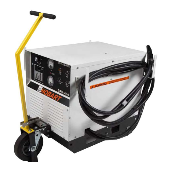
- Page 21 Specifications and Capabilities Table in Figure 2. This book will generally refer to this equipment as a GPU-600 power sup- ply or power supply. See Figure 1 for a descriptive drawing showing the major components or sub-assem- blies generally present in the design.
- Page 22 3. Caster 9. Front Access Door 4. Front Panel 10. Rear Access Door 5. Rear Panel 11. Lifting Yoke 6. Cable Hanger 12. Power Receptacle 7. Top Panel General Assembly of GPU-600 Power Supply Figure 1 April 10/89 Revised Page 2...
- Page 23 OM-2010 H. Various internal components such as the preload resistors (6, Fig. 3), main transformer (1, Fig. 3), filter capacitors (4, Fig. 3) with the bus bar (5, Fig. 3) at the front, filter reactor (7, Fig. 3), two (8, 9, Fig.
- Page 24 OM-2010 PHYSICAL Weight (approximately) 650 pounds (295 kg) Length 38 1/8 inches (968 mm) Width 32 3/4 inches (832 mm) Height (overall) 34 1/8 inches (867 mm) ELECTRICAL SPECIFICATION NUMBER INPUT S6883-1 S6883-2 S6883A-1 * S6883A-1 * S6883A-1 * Cycles per second Phase Volts 208/230/460...
- Page 25 OM-2010 3. Detailed Description A. General A detailed description of the parts used to build the power supply is given below. If a description ap- plies only to power supplies having a particular specification number, reference to that specification will be made. The specification number and equipment rating information is provided on the name- plate located on the power supply front panel just above the manufacturers name.
- Page 26 17. SCR Heat Sink Assembly 7. Choke 18. Fan Blade 8. (Deleted) 19. Fan Motor 9. 28 V-DC Contactor 20. Control Transformer Fuse 10. Control Transformer 21. Ammeter Shunt 11. Right Side Panel Internal Components for GPU-600 Figure 3 April 10/89 Revised Page 6...
- Page 27 4. DS2 Overload Light 11. S2 Output On-Off Switch 5. 115 VAC Receptacle 12. Input Power Light (amber) 6. MOV Surge Suppressor 13. Output Contactor Light (green) 7. 115 VAC Weather Cover Front Panel Assembly, GPU-600 Figure 4 April 10/89 Revised Page 7...
- Page 28 OM-2010 The main transformer of the 208/230/460-V power supply (Spec 6683-1 or 6883A-1) has a winding to provide the 115-V AC for the auxiliary power receptacle and fan motor. The main transformer has a center tapped coil on each phase that provides six sensing or synchronizing voltage signals to the solid state printed circuit control board (13, Fig.
- Page 29 OM-2010 F. Output Filter Circuitry The DC output voltage is smoothed (filtered) by an L-C filter made up of L1 iron core reactor (7, Fig. 3) carrying the output current to the load and the ripple current to the C15, C16, C17 ripple bypass ca- pacitors (4, Fig.
- Page 30 OM-2010 (4) Overload Trip Light (4, Fig. 4) The overload trip light glows whenever the solid state printed circuit board turns off the power sup- ply output due to output voltage exceeding 31.5 V DC, output current surge exceeding 2200-A H.Main SCR Heat Sink Assembly (See Fig.
- Page 31 OM-2010 (4) Thermal Overload Trip The printed circuit board turns off the SCR firing or gate pulses and turns on the trip light when S5 overload thermostat (3, Fig. 5) opens. The power supply can not produce any DC output until the S5 thermostat cools enough to automatically reset (close).
- Page 32 OM-2010 This page intentionally left blank April 10/89 Revised Page 12...
- Page 33 OM-2010 CHAPTER 2. DESCRIPTION AND OPERATION SECTION 2. OPERATION 1. General This section contains information for safe and efficient operation of the equipment. Operating instructions are presented in step-by-step sequence of procedures to be followed in supplying 28 V DC to an aircraft or similar load.
- Page 34 OM-2010 3. Operation Procedure A. Input Control Functions (1) Turn on S1 input contactor switch (4, Fig. 1). (2) Verify that only the amber input power light (7, Fig. 1) glows. If the light glows, no problem exists requiring service. B.
- Page 35 OM-2010 1. Front Panel 8. Red Overload Trip Light, DS2 2. Control Fuse, F1 (15A) 9. Start Current Potentiometer, R13 3. Input ON-OFF switch, S1 10. Green Output Contactor Light, DS3 4. Output Contactor Switch, S2 11. Auxiliary Power Receptacle, 115V-AC 5.
- Page 36 OM-2010 This page intentionally left blank. April 10/89 Revised Page 4...
- Page 37 OM-2010 CHAPTER 3. SERVICING SECTION 1. MAINTENANCE 1. General To be certain the DC power supply set is ready for operation at all times, it must be inspected and main- tained systematically so that defects may be discovered and corrected before they result in serious dam- age or failure of the equipment.
- Page 38 OM-2010 4. Parts Replacement A. Minor electrical components (1) Lamps and fuses are mortality type items which require simple periodic replacement. (2) Switches, meters, contactors and fan motor in the power supply fall into the category of parts which can be expected to fail at infrequent, irregular intervals. Instructions for repair and replace- ment of these parts are obvious.
- Page 39 OM-2010 Section 2. INSPECTION CHECK AND REPAIR 1. General This section describes inspections and checks to be performed in conjunction with Inspection/Check Schedule, Figure 1. For satisfactory service, keep the power supply clean, dry, and well ventilated. At the prescribed intervals or more often as necessary, disconnect the power supply from the input power source and wipe and blow out all dirt and other foreign materials from the internal components, including the fan blades.
- Page 40 OM-2010 (2) Overload trip indicating light More than 31.5 V DC output or overcurrent trips overload trip light DS2. The light emitting diode circuit resets when S1 power on switch is cycled off and back on after the cause of the trip has been removed.
- Page 41 OM-2010 DAILY 1 MONTH 3 MONTH 6 MONTH REQ'D 8 HRS. 200 HRS. 600 HRS. 1200 HRS. * EXTERIOR CABLES Inspect equipment output cables Inspect AC input cables Check cable connections (internal) * CONTROLS AND INSTRUMENTS Check voltmeter functioning Check ammeter functioning Check fan thermostat operation Check indicating lights...
- Page 42 OM-2010 E. Contactors (1) Output Contactor, K2 The output contactor has contacts that can be visually inspected whenever the input power is re- moved from the power supply. If the contacts are badly burned the contactor should be replaced as soon as possible. Slightly pitted and burned contacts can be cleaned up with a commercial contact cleaner and very fine grained emery cloth or equivalent.
- Page 43 7.05 newton meters). If the SCR bridge has one or more SCR devices showing a short circuit or low ohmmeter reading, it is recommended that the GPU-600 power supply be sent to the factory or an authorized repair station for repair. A replacement SCR bridge subassembly can be ob- tained from the factory which would allow the customer to replace the faulty SCR bridge assem- bly without special tools and techniques.
- Page 44 OM-2010 (3) Voltage Test for SCR Assembly With input power turned off, reconnect one SCR device at a time and apply power until the input power is interrupted by a fault condition or all the SCR devices are connected. The last SCR de- vice to be connected before interruption is faulty.
- Page 45 OM-2010 (e) If the reason the pc control board is being checked, and no substitute board exists, is insuffi- ciency of output voltage with proper AC secondary voltage at the main transformer, check for proper pc board voltages (See 3-3), if no oscilloscope is available. If the readings are good, the problem may be one or more open SCR devices.
- Page 46 OM-2010 This page intentionally left blank April 10/89 Revised Page 8...
- Page 47 This section describes the test points, test values, and adjustment locations for testing and adjusting the printed circuit control board which is the “brains” of the GPU-600 DC power supply. As a minimum the following equipment and tools are required.
- Page 48 OM-2010 CAUTION: IMPROPER TEST EQUIPMENT CAN DAMAGE! USE ONLY RECOMMENDED TEST EQUIPMENT AND TOOLS. NEVER APPLY TEST VOLTAGE DIRECTLY TO COMPONENTS ON THE BOARD. THIS SOLID STATE CONTROL USES LOW CURRENT DEVICES THAT QUICKLY BURN OUT IF A LOW IMPEDANCE VOLTAGE SOURCE IS APPLIED DIRECTLY TO THE COM- PONENT.
- Page 49 OM-2010 1. TP1 SCR Gate Pulse from R10 13 TP14 Null at 0 A DC TP, (R38) * Adjust. 14. R60 Overload Limit, (TP20) 2. TP2 SCR Gate Pulse from R9 15. R109 28 V DC Output Cal., (TP13) Adjust. 3.
- Page 50 OM-2010 Test Value and Comment Tabulation (For PC Board No. 180294A) Figure 2 (Sht. 1 of 2) April 10/89 Revised Page 4...
- Page 51 OM-2010 Test Value and Comment Tabulation (For PC Board No. 180294) Figure 2 (Sht. 2 of 2) April 10/89 Revised Page 5...
- Page 52 OM-2010 This page intentionally left blank April 10/89 Revised Page 6...
- Page 53 OM-2010 SECTION 4. TROUBLESHOOTING 1. General A. Troubleshooting is an orderly process of checking and eliminating possible causes of trouble until the exact cause of a trouble is found. As a rule, the best place to start looking for the cause of a trouble in a circuit is at the source of power.
- Page 54 OM-2010 (4) Always check circuit fuses, circuit breakers and the position of switches first in troubleshooting. The incorrect positioning of a switch may cause a condition which could be misinterpreted as a fault. (5) Electrical component symbols, which are used on schematic diagrams, and their legends to iden- tify components, may be used in the troubleshooting chart (in parentheses after the item name) to help maintenance personnel identify parts on the schematic diagrams.
- Page 55 OM-2010 6. SCR Malfunction Instructions A. Normal SCR Malfunction Conditions (1) Blown line fuses as the result of a shorted SCR (similar to a shorted diode) . A shorted flyback di- ode will also produce this situation. This is a severe malfunction. See 6B. (2) If one SCR does not turn on [(either it is open or the gate signal is not being received by the SCR (gate circuit open)], a very small change will occur at the output which will be difficult to notice.
- Page 56 OM-2010 TROUBLE, SYMPTOM AND CONDITION PROBABLE CAUSE TEST, CHECK, AND/OR REMEDY MACHINE WILL NOT OPERATE 1. Machine will not start. Step 1. Input power turned OFF at Remote Disconnect Switch. Turn power ON at Remote Disconnect Switch. Step 2. Blown fuse in Remote Disconnect Switch. Replace blown fuse.
- Page 57 OM-2010 TROUBLE, SYMPTOM AND CONDITION PROBABLE CAUSE TEST, CHECK, AND/OR REMEDY MACHINE WILL NOT OPERATE (CONTINUED) 2. Line contactor fails to close (continued) Step 4. Defective coil in line contactor. Replace contactor if coil is open or shorted. Step 5. Cable broken at line contactor. Repair broken cable as necessary.
- Page 58 OM-2010 TROUBLE, SYMPTOM AND CONDITION PROBABLE CAUSE TEST, CHECK, AND/OR REMEDY MACHINE WILL NOT OPERATE (CONTINUED) 4. Contactor operates and blows line fuses. (Continued) Step 2. Line fuses too small. Install fuses of proper amperage rating. Refer to Section 1-2, Fig. 1 for proper fuse size. Step 3.
- Page 59 OM-2010 TROUBLE, SYMPTOM AND CONDITION PROBABLE CAUSE TEST, CHECK, AND/OR REMEDY UNIT TRIPS OUT AFTER STARTING (CONTINUED) Step 3. Ambient temperature too high. Operate at reduced loads when temperature exceeds 104F (40C) or improve cooling ambient. Step 4. Ventilation blocked. Check that air intake and exhaust openings are not obstructed.
- Page 60 OM-2010 TROUBLE, SYMPTOM AND CONDITION PROBABLE CAUSE TEST, CHECK, AND/OR REMEDY UNIT TRIPS OUT AFTER STARTING. (CONTINUED) 3. Fan not operating (also see causes and remedies under “Machine will not start”). Step 1. Blown fuse (F1) on front panel of machine. Replace fuse.
- Page 61 OM-2010 TROUBLE, SYMPTOM AND CONDITION PROBABLE CAUSE TEST, CHECK, AND/OR REMEDY POWER SUPPLY WILL NOT TURN OFF 1. Contactor fails to open. Step 1. Contacts sticking in contactor. Clean contacts or replace contactor, whichever is needed. POWER SUPPLY ON: NO VOLTAGE OUTPUT Step 1.
- Page 62 OM-2010 TROUBLE, SYMPTOM AND CONDITION PROBABLE CAUSE TEST, CHECK, AND/OR REMEDY OUTPUT VOLTAGE NOT PROPER LEVEL 1. Poor voltage regulation. Step 1. Loose connection of voltage sensing lead. Check connection at output contactor and control circuit board. Tighten connection as necessary. 2.
- Page 63 The Illustrated Parts List identifies, describes, and illustrates main assemblies, subassemblies, and detail parts of the GPU-600 Series, SCR Phase controlled, DC power supply manufactured by Ground Power Group, Hobart Brothers Company, Troy, Ohio, and identified as Specification No. S6683 or 6883A with ap- plicable dash number.
- Page 64 (2) “HOBART PART NUMBER” Column ALL part numbers appearing in this column are Hobart numbers. In all instances where the part is a purchased item, the vendor’s identifying fivedigit code and his part number will appear in the “NOMENCLATURE”...
- Page 65 OM-2010 SECTION 2. MANUFACTURER’S CODES 1. Explanation of Manufacturer’s (Vendor) Code List The following list is a compilation of vendor codes with names and addresses for suppliers of purchased parts listed in this publication. The codes are in accordance with the Federal Supply Codes for Manufac- turer’s Cataloging Handbook H4-1, and are arranged in numerical order.
- Page 66 OM-2010 CODE VENDOR’S NAME AND ADDRESS 51285 Woodrow Mfg. Company, 4300 River Rd., P.O. Box 1567, Springfield, Ohio 45501 56289 Sprague Electric Company, 87 Marshall St., North Adams, Mass. 01247 60741 Triplett Electrical Instrument Company, Harmon Road, Bluffton, Ohio 45817 62119 Universal Electric Company, 300 E.
- Page 67 OM-2010 SECTION 3. PARTS LIST 1. Explanation of Parts List Arrangement The parts list is arranged so that the illustration will appear on a left-hand page and the applicable parts list will appear on the opposite right-hand page. Unless the list is unusually long, the user will be able to look at the illustartion and read the parts list without turning a page.
- Page 68 OM-2010 General Assembly GPU-600 Figure 1 August 24/89 Revised Page 2...
- Page 69 OM-2010 NOMENCLATURE UNITS FIGURE HOBART ITEM NO. PART NO. 1234567 ASSY S-6883-1 GPU-600, 60-Hz, 208/230/460 VAC S-6883-2 GPU-600, 50-HZ, 220/380 VAC S-6883A-1 GPU-600, 60-Hz, 208/230/460 VAC S-6883A-2 GPU-600, 50-HZ, 220/380 VAC S-6883A-3 GPU-600, 60-Hz, 230/460/575 VAC 12CW-2170 . GROMMET, TOP 489584 .
- Page 70 OM-2010 This page intentionally left blank. August 24/89 Revised Page 4...
- Page 71 OM-2010 NOMENCLATURE UNITS FIGURE HOBART ITEM NO. PART NO. 1234567 ASSY (Continued) W-11242-14 . WASHER, FLAT W-11338-3 . COTTER PIN 83B-1100-1 . CASTER MATERIAL HANDLING ASSOC, NO. 6-43-126-7 83B-1100-2 . CASTOR WITH BRAKE, NO. 6-43-126-7 MATERIAL HANDLING ASSOC. 910225-1 . HANDLE ASSY.
- Page 72 OM-2010 Lifting Yoke Assembly Figure 2 August 24/89 Revised Page 6...
- Page 73 OM-2010 NOMENCLATURE UNITS FIGURE HOBART ITEM NO. PART NO. 1234567 ASSY 489591 YOKE, LIFTING ASSY. (For NHA See Fig. 1) 180364 YOKE, LIFTING ASSY. (For NHA See Fig. 1) 489582 . . YOKE LIFTING 406392-1 . . TRANSFORMER, CONTROL, V97520, NO.
- Page 74 OM-2010 SCR Heat Sink Assembly Figure 3 August 24/89 Revised Page 8...
- Page 75 OM-2010 NOMENCLATURE UNITS FIGURE HOBART ITEM NO. PART NO. 1234567 ASSY 489700 RECTIFIER, OUTPUT ASSEMBLY, (For NHA See Fig. 1) 367634A-3 . . SUPPRESSOR, SURGE ASSY 200880 . . HEAT SINK, RECTIFIER 404044-3 . . THERMOSTAT, OVERLOAD, 02907, V14604, NO. 2450-82-175 406990 .
- Page 76 OM-2010 Front Panel Assembly Figure 4 August 24/89 Revised Page 10...
- Page 77 OM-2010 NOMENCLATURE UNITS FIGURE HOBART ITEM NO. PART NO. 1234567 ASSY 489588-1 PANEL, FRONT ASSY (For NHA See Fig. 1) 489588-2 PANEL, FRONT ASSY (For NHA See Fig. 1) 489587 . . PANEL, FRONT 180373 . . PANEL, FRONT 408446 .
- Page 78 OM-2010 This page intentionally left blank. August 24/89 Revised Page 12...
- Page 79 OM-2010 SECTION 4. NUMERICAL INDEX 1. Explanation of Numerical Index The purpose of this index is to assist the user in finding the illustration and description of a part when the part number is known. Part numbers are arranged in alpha-numerical sequence. Thus, any part number beginning with the letter A would be located at or near the top of the index list.
- Page 80 OM-2010 NUMERICAL INDEX FIGURE AND PART NUMBER ITEM NUMBER 369639 1-22 369641 3-10 397752-1 1-26 400400 4-11 400613-3 4-22 400613-6 4-14 400641-11 4-20 400642-3 4-16 400647-8 4-24 400663 401428-1 401532-2 402197-1 402670 402658 4-18 403189 4-10 403247 4-15 403765-2 1-25 403870-3 403955-3 404044-3...
- Page 81 OM-2010 NUMERICAL INDEX FIGURE AND PART NUMBER ITEM NUMBER 487050-2 RESISTOR ASSY. 487801 2-12 487813 1-12 487815 2-11 487897 2-16 487898 2-18 487905 1-18 487906 1-19 487952 1-16 487964 1-42 487979 1-41, 2-14 489561 1-13 489573 1-10 489581 4-23 489582 489584 489586 489587...
- Page 82 OM-2010 This page intentionally left blank. April 10/89 Revised Page 4...
- Page 83 OM-2010 CHAPTER 5. OPTIONAL EQUIPMENT Optional Equipment available for use with GPU-400 is listed below. OPTION PART No. MANUAL No. Kit, Riser 284535 TO-231 December 17/93 Revised Page 1...
- Page 84 OM-2010 This page intentionally left blank April 10/89 Revised Page 2...
- Page 85 OM-2010 CHAPTER 6. MANUFACTURER’S LITERATURE DIAGRAMS FOR 6883-1 489595 Schematic 489596 Connection 489594 Voltage Changeover DIAGRAMS FOR 6883-2 180368 Schematic 180369 Connection 180367 Voltage Changeover DIAGRAMS FOR 6883A 489595 Schematic 489596 Connection 181566 Voltage Changeover April 10/89 Revised Page 1...
- Page 86 OM-2010 This page intentionally left blank. April 10/89 Revised Page 2...
- Page 101 UNUSUAL SERVICE CONDITIONS This information is a general guideline and cannot cover all possible conditions of equipment use. The specific local environments may be dependent upon conditions beyond the manufacturer’s control. The manufacturer should be consulted if any unusual conditions of use exist which may affect the physical condition or operation of the equipment.
- Page 102 This page intentionally left blank...
Need help?
Do you have a question about the GPU-600 and is the answer not in the manual?
Questions and answers