
Related Manuals for Lochinvar COPPER-FIN CW 645


Summary of Contents for Lochinvar COPPER-FIN CW 645
- Page 1 DESIGNER’S GUIDE COPPER-FIN ® WATER HEATER 4 9 5 , 0 0 0 – 2 , 0 6 5 , 0 0 0 B t u / h r...
- Page 2 The designer’s guide you are now holding has been designed to make it more convenient for you to select the perfect Lochinvar water heater for your projects and provide correct specifications for your teams. All information has been organized and presented in a succinct, easy-to-use manner, so you can use and share information confidently and with minimal effort.
-
Page 3: Table Of Contents
TABLE I. Amp Draw ....14 Appendix A - Water Heater Piping Diagrams Single Heater – Single Tank ..A1 Single Heater – Two Tanks ..A2 Two Temperature Installation Single Heater –... -
Page 4: Codes
Lochinvar In designing a water heater system, pay special attention to: Water Velocity (See page 12 for Required Degree Rise chart.) Factory Supplied Pump Capacity (See page 12 for Pump Operation.) Manifold Pipe Size When using more than one heater... -
Page 5: Table A. Clearances From Combustible
The indoor units must be installed so that the ignition system components are protected from water (dripping, spraying, rain, etc.) during appliance operation and service (circulator replacement, control replacement, etc.). The appliance must be installed on a level, non-combustible floor. Concrete over wood is not considered a non-combustible floor. - Page 6 OUTLET FRONT COLD WATER INLET BURNER INSPECTION PORT (FIG. 2) WATER HEATER EQUIPMENT AND CONTROL ORIENTATION. L o c h i n v a r D E S I G N E R RIGHT SIDE INLET GAS CONNECTION FRESH AIR...
-
Page 7: Combustion & Ventilation Air
F I N W A T E R H E A T E R EXAMPLE OF SIZING FOR COMBUSTION & VENTILATION AIR OPENINGS (WATER HEATER WITH 2,065,000 Btu/hr INPUT): When combustion and ventilated air is taken from directly outside the building (FIG. -
Page 8: Contaminants
If a fan is used water heater, cause improper combustion to supply combustion air to the equipment and premature failure of the water heater room, it must by sized and vent. such to make sure that it does not cause drafts... -
Page 9: Vent Terminations
National Fuel Gas Code. The weight of the venting system must not rest on the water heater. The venting system must be adequately supported in compliance with local codes and other applicable codes. -
Page 10: Installation
Lochinvar must be consistent with the National Fuel NOTE: Gas Code Z223.1 or in Canada, the latest A vent system should edition of CGA Standard B149 Installation never be sized based Code for Gas Burning Appliances and only on the vent Equipment. -
Page 11: Fig. 8 Multiple Unit Barometric Damper Installation
Units are self venting and can be used outdoors when installed with the optional Outdoor Cap. This cap mounts directly to the top of the water heater and covers the flue outlet and combustion air inlet openings on the jacket. No additional vent piping is required. -
Page 12: Gas Supply
Do not install in locations where rain from building runoff drains will spill onto the water heater. Lochinvar must furnish an outdoor vent kit in accordance with CSA international requirements. Each kit includes the flue outlet/combustion air inlet, assembly, gasket and pump cover. -
Page 13: Table D. Gas Supply Pipe Sizing
WATER CONNECTIONS Inlet and Outlet Water Connections For ease of service, install unions on inlet and outlet of the water heater. The connection on the unit marked “Inlet” should be used for return water from the storage tank. The connection on the header marked “Outlet”... -
Page 14: Table F. Required Temperature Rise
The mixing valve allows the water heater to operate above 140°F to protect from condensation, while still allowing a delivery of colder water to the system fixtures. Also... -
Page 15: Table G. Required Pump Performance
’ D E S I G N E R S G U I D E C O P P E R Standard production Lochinvar water heaters are designed to operate free of impurity build-up in the heat exchanger when properly installed and operated under the specified water quality conditions. -
Page 16: Table I. Amp Draw
T wire [63°F (35°C) rise]. The pump must be wired to run continuously when unit is firing. COMMON MANIFOLD SIZE It is recommended that the water heater (Min.) and pump be wired on separate circuits 2” with properly sized breakers. -
Page 17: Water Heater Piping Diagrams
UNION EXPANSION 6 1 5 - 8 8 9 - 8 9 0 0 F I N W A T E R H E A T E R SINGLE HEATER - SINGLE TANK LOCHINVAR WATER HEATER INLET BUILDING RETURN LIT0133... -
Page 18: Single Heater - Two Tanks
FULL PORT SYSTEM SYSTEM BALL VALVE PUMP RELIEF VALVE L o c h i n v a r D E S I G N E R LOCHINVAR WATER HEATER OUTLET INLET L E G E N D ELBOW UNION ’... -
Page 19: Two Temperature Installation Single Heater - Single Tank
FULL PORT SYSTEM SYSTEM BALL VALVE PUMP RELIEF VALVE Lochinvar ’ D E S I G N E R S G U I D E C O P P E R TWO TEMPERATURE INSTALLATION - SINGLE HEATER-SINGLE TANK LOCK-TEMP STORAGE TANK... -
Page 20: Two Heaters-Single Tank
SUPPLY DRAIN BUILDING RETURN Gray shaded area represents common manifold piping. COMMON WATER MANIFOLD SIZE FOR MULTIPLE WATER HEATER INSTALLATION Pipe sizing chart provides minimum pipe size for common manifold piping to ensure adequate flow. NUMBER OF UNITS CW 495-745 This illustration is for concept only and should not be used for any actual installation without engineering or technical advice from a licensed engineer. -
Page 21: Two Heaters-Two Tanks
STORAGE TANKS DRAIN Gray shaded area represents common manifold piping. COMMON WATER MANIFOLD SIZE FOR MULTIPLE WATER HEATER INSTALLATION Pipe sizing chart provides minimum pipe size for common manifold piping to ensure adequate flow. NUMBER OF COMMON MANIFOLD SIZE UNITS... -
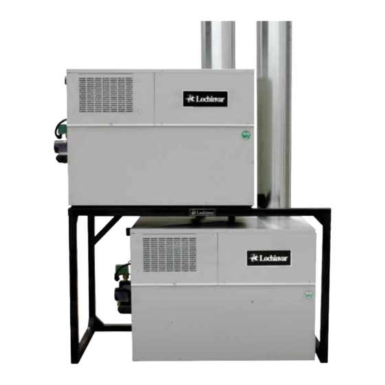
Page 22: Multi-Stack Frame
PIPING DIAGRAM L o c h i n v a r D E S I G N E R MULTI-STACK FRAME W/ WATER HEATERS AND STORAGE TANK Heater Heater Inlet/ Model Outlet Size CW495-745 2” CW986-2066 2-1/2” ’ S G U I D E C O P P E R F I N W A T E R H E A T E R Manifold Pipe Size... - Page 24 Lochinvar Corporation • Lebanon, TN • 615-889-8900 / Fax: 615-547-1000 www.Lochinvar.com CW-DG-05 4/09-Printed in U.S.A. (Revised CW-DG-05 1/07)
Need help?
Do you have a question about the COPPER-FIN CW 645 and is the answer not in the manual?
Questions and answers