Table of Contents
Advertisement
Quick Links
Models:
GDCH60 Series
GDST60 Series
GDFL60 Series
GDCR60 Series
GDCL60 Series
Direct Vent Gas Appliance
• Important operating and
maintenance instructions
included.
WARNING
If the information in these instruc-
tions is not followed exactly, a
fi re may result causing property
damage, personal injury, or death.
• Do not store or use gasoline or other fl am-
mable vapors and liquids in the vicinity of
this or any other appliance.
• What to do if you smell gas:
- Do not try to light any appliance.
- Do not touch any electrical switch. Do not
use any phone in your building.
- Immediately call your gas supplier from
a neighbor's phone. Follow the gas
supplier's instructions.
- If you cannot reach your gas supplier, call
the fi re department.
• Installation and service must be performed
by a qualifi ed installer, service agency, or
the gas supplier.
This appliance may be installed as an OEM installation in manufactured
home (USA only) or mobile home and must be installed in accordance
with the manufacturer's instructions and the manufactured home
construction and safety standard, Title 24 CFR, Part 3280 or Standard
for Installation in Mobile Homes, CAN/CSA Z240MH.
This appliance is only for use with the type(s) of gas indicated on the
rating plate.
DO NOT DISCARD THIS MANUAL
Read, understand and follow
•
these instructions for safe
installation and operation.
Heatilator • Caliber Multi-Sided Direct Vent • 4002-079 Rev K • 11/07
GDCH60 shown
CAUTION
Leave this manual with
•
party responsible for
use and operation.
• CAREFULLY SUPERVISE children in same room as
appliance.
• A l e r t c h i l d r e n a n d a d u l t s t o h a z a r d s o f h i g h
temperatures.
High temperatures may ignite clothing or other
fl ammable materials.
• Keep clothing, furniture, draperies and other combustibles
away.
This appliance has been supplied with an integral
barrier to prevent direct contact with the fi xed glass
panel. Do NOT operate the appliance with the barrier
removed.
Contact your dealer or Hearth & Home Technologies if the
barrier is not present or help is needed to properly install one.
In the Commonwealth of Massachusetts installation must
be performed by a licensed plumber or gas fi tter;
See Table of Contents for location of additional
Commonwealth of Massachusetts requirements.
Installation and service of this appliance should be performed
by qualifi ed personnel. Hearth & Home Technologies suggests
NFI certifi ed or factory-trained professionals, or technicians
supervised by an NFI certifi ed professional.
Owner's Manual
Installation and Operation
WARNING
HOT SURFACES!
Glass and other surfaces are hot during
operation and cool down.
Hot glass will cause burns.
• Do not touch glass until it is cooled
• NEVER allow children to touch glass
• Keep children away
1
Advertisement
Table of Contents

Subscribe to Our Youtube Channel
Related Manuals for Heatilator GDCH60 Series


Summary of Contents for Heatilator GDCH60 Series
- Page 1 This appliance is only for use with the type(s) of gas indicated on the by qualifi ed personnel. Hearth & Home Technologies suggests rating plate. NFI certifi ed or factory-trained professionals, or technicians supervised by an NFI certifi ed professional. Heatilator • Caliber Multi-Sided Direct Vent • 4002-079 Rev K • 11/07...
- Page 2 DO NOT REMOVE OR COVER THIS LABEL. VENTED GAS FIREPLACE - NOT FOR USE WITH SOLID FUEL. FOYER À GAZ À ÉVACUATION - NE DOIT PAS ÊTRE UTILISÉ AVEC UN COMBUSTIBLE SOLIDE. Heatilator • Caliber Multi-Sided Direct Vent • 4002-079 Rev K • 11/07...
-
Page 3: Table Of Contents
D. High Altitude Installations ..... 36 Note: An arrow ( ) found in the text signifi es change in content. Heatilator • Caliber Multi-Sided Direct Vent • 4002-079 Rev K • 11/07... -
Page 4: Listing And Code Approvals
Immediately call a qualifi ed service technician to inspect the appliance and to replace any part of the control system and any gas control which has been under water. Heatilator • Caliber Multi-Sided Direct Vent • 4002-079 Rev K • 11/07... -
Page 5: Requirements For The Commonwealth Of Massachusetts
See Gas Connection section for additional Common- less than one-half (1/2) inch in size, “GAS VENT wealth of Massachusetts requirements. DIRECTLY BELOW. KEEP CLEAR OF ALL OBSTRUC- TIONS”. Heatilator • Caliber Multi-Sided Direct Vent • 4002-079 Rev K • 11/07... -
Page 6: Getting Started
Safety glasses Level Manometer Voltmeter Tape measure Non-corrosive leak check solution 1/2 - 3/4 in. length, #6 or #8 Self-drilling screws One 1/4 in. female connection (for optional fan). Heatilator • Caliber Multi-Sided Direct Vent • 4002-079 Rev K • 11/07... -
Page 7: Framing And Clearances
(305 mm) (305 mm) 36 in. 45-1/4 in. 36 in. (914 mm) (1149 mm) (914 mm) GDFL60 GDFL60 (using a Catalina Shelf and/or Marble Package) Figure 3.1 Appliance Locations Heatilator • Caliber Multi-Sided Direct Vent • 4002-079 Rev K • 11/07... - Page 8 Header - 26 in. x 8 in. Side Headers - 45-1/2 in. x 8 in. Legs - 33-1/2 in. x 7 in. Thickness: 1/4 in. Figure 3.2 Catalina Package Dimensions Heatilator • Caliber Multi-Sided Direct Vent • 4002-079 Rev K • 11/07...
-
Page 9: Construct The Appliance Chase
(i.e., steel studs, concrete board, etc.). Failure to comply may cause fi re. Heatilator • Caliber Multi-Sided Direct Vent • 4002-079 Rev K • 11/07... -
Page 10: Clearances
Note: When installing these appliances, do not cover or frame in the lower panels of the appliance. This will interfere with proper operation of glass assemblies and access to the control panel. Heatilator • Caliber Multi-Sided Direct Vent • 4002-079 Rev K • 11/07... -
Page 11: Termination Locations
Fire Risk Explosion Risk Inspect external vent cap regularly. • Ensure no debris blocks cap. • Combustible materials blocking cap may ignite. • restricted air flow affects burner operation. Heatilator • Caliber Multi-Sided Direct Vent • 4002-079 Rev K • 11/07... - Page 12 A Gas Termination Wood or Fuel Oil Termination tions supplied with the decorative cap cover. 6 in. 20 in. (152 mm) min. (508 mm) min. Figure 4.3 Multiple Vertical Termination Heatilator • Caliber Multi-Sided Direct Vent • 4002-079 Rev K • 11/07...
- Page 13 N Vertical clearance between two horizontal termination caps – 12 in. (30 these requirements. cm) minimum. O Horizontal clearance between two horizontal termination caps – 12 in. (30 cm) minimum. Figure 4.4 Minimum Clearances for Terminations Heatilator • Caliber Multi-Sided Direct Vent • 4002-079 Rev K • 11/07...
-
Page 14: Vent Information And Diagrams
8-1/2 in. vertical run. A length of straight pipe is allowed DVP Pipe (see chart) between two 45° elbows (see Figure 5.1). Figure 5.2 DVP Pipe Effective Length Heatilator • Caliber Multi-Sided Direct Vent • 4002-079 Rev K • 11/07... -
Page 15: Vent Diagrams
24 in./610 mm 25 ft/7.62 m 25 ft/7.62 m 25 ft/7.62 m You may install the elbow directly on top of the appliance. Figure 5.3 Top Vent-Horiztonal Termination-One Elbow Heatilator • Caliber Multi-Sided Direct Vent • 4002-079 Rev K • 11/07... - Page 16 See Figure 5.6 for information about installing elbows horizontally. Table 5.2 min. max. H max. 12 in./305 mm 24 ft/7.32 m 19 ft/5.79 m Installed Vertically Figure 5.5 Three Vertically Installed 90° Elbows Heatilator • Caliber Multi-Sided Direct Vent • 4002-079 Rev K • 11/07...
- Page 17 24 in./810 mm 25 ft/7.62 m 25 ft/7.62 m 25 ft/7.62 m 25 ft/7.62 m 25 ft/7.62 m Installed Vertically Installed Horizontally Figure 5.6 Two or Three Elbows, some Horizontal Heatilator • Caliber Multi-Sided Direct Vent • 4002-079 Rev K • 11/07...
- Page 18 12 ft (3.66 m) min. 60 ft (18.29 m) max. Maximum horizontal run is 100% of vertical, but cannot exceed 26 ft (7.92 m) Figure 5.8 Vertical Termination - Two Elbows Heatilator • Caliber Multi-Sided Direct Vent • 4002-079 Rev K • 11/07...
- Page 19 60 ft (18.29 m) max. Figure 5.9 Vertical Termination - Three Elbows (some horizontal) Rear Vent—Horizontal Termination—No Elbow 18 in. (457 mm) max. Figure 5.10 Horizontal Termination - No Elbows Heatilator • Caliber Multi-Sided Direct Vent • 4002-079 Rev K • 11/07...
- Page 20 8 ft/2.44 m 12 in./305 mm 48 in./1219 mm 8 ft/2.44 m 24 in./610 mm 48 in./1219 mm 8 ft/2.44 m Figure 5.12 Horizontal Termination - Two Elbows Heatilator • Caliber Multi-Sided Direct Vent • 4002-079 Rev K • 11/07...
- Page 21 6 ft/1.83 m 12 in./305 mm 48 in./1219 mm 6 ft/1.83 m 24 in./610 mm 48 in./1219 mm 6 ft/1.83 m Figure 5.13 Horizontal Termination - Three Elbows Heatilator • Caliber Multi-Sided Direct Vent • 4002-079 Rev K • 11/07...
- Page 22 6 ft (1.83 m) max. 60 ft (18.29 m) max. Maximum horizontal run is 100% of vertical, but cannot exceed 26 ft (7.92 m) Figure 5.15 Vertical Termination - Two Elbows Heatilator • Caliber Multi-Sided Direct Vent • 4002-079 Rev K • 11/07...
-
Page 23: Vertical Termination - Three Vertical Elbows
60 ft (18.29 m) max. Maximum horizontal run is 100% of vertical, but can- not exceed 26 ft (7.92 m). Figure 5.16 Vertical Termination - Three Vertical Elbows Heatilator • Caliber Multi-Sided Direct Vent • 4002-079 Rev K • 11/07... -
Page 24: Vent Clearances And Framing
If your local inspector requires the wall shield fi restop on both sides of the wall, then both wall shield fi restops must have a heat shield attached to them. Figure 6.3 Exterior Wall Hole Heatilator • Caliber Multi-Sided Direct Vent • 4002-079 Rev K • 11/07... -
Page 25: Install The Ceiling Firestop
3 fasteners per side Ceiling firestop Ceiling firestop installed below ceiling. installed above ceiling. Figure 6.5 Installing Ceiling Firestop & Attic Insulation Shield Heatilator • Caliber Multi-Sided Direct Vent • 4002-079 Rev K • 11/07... -
Page 26: Install Attic Insulation Shield
Bend all tabs inward 90° around the top of the shield. These tabs must be used to prevent blow-in insulation from getting between the shield and vent pipe, and to maintain clearance. Heatilator • Caliber Multi-Sided Direct Vent • 4002-079 Rev K • 11/07... -
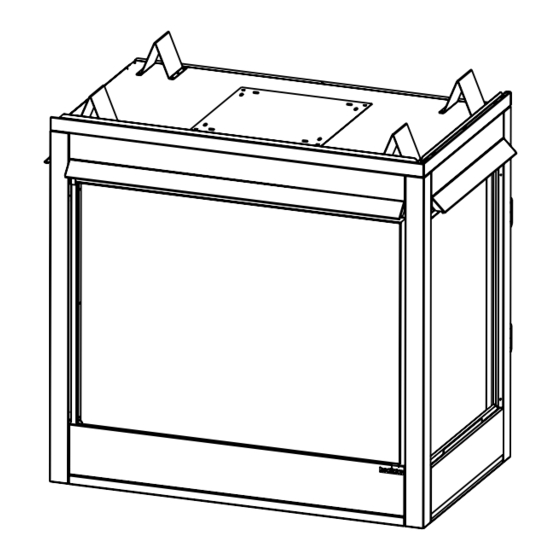
Page 27: Appliance Preparation
7.4. Remove outer shell cover and set aside. (Cover has insulation attached.) Figure 7.1 Cover Plate - Remove Four Screws Figure 7.4 Outer Shell Cover - Remove Four Screws Heatilator • Caliber Multi-Sided Direct Vent • 4002-079 Rev K • 11/07... - Page 28 Place inner cover plate on appliance top and replace four screws to hold inner cover plate in place. See Figure 7.10. Figure 7.7 Attach Inner Collar Figure 7.10 Attach Inner Cover Plate Heatilator • Caliber Multi-Sided Direct Vent • 4002-079 Rev K • 11/07...
-
Page 29: Securing And Leveling The Appliance
Secure the appliance to the framing by using nails or screws through the nailing tabs. CAUTION Do NOT notch into the framing around the appliance Figure 7.13 Proper Positioning, Leveling and Securing of an spacers. Appliance Heatilator • Caliber Multi-Sided Direct Vent • 4002-079 Rev K • 11/07... -
Page 30: Installing Vent Pipe
fl ues shall be sealed in this manner, unless otherwise stated. Note: The end of the pipe sections with the lances/tabs on it will face towards the appliance. Figure 8.2 Inner/Outer Figure 8.3 Snapped Heatilator • Caliber Multi-Sided Direct Vent • 4002-079 Rev K • 11/07... - Page 31 Only outer pipes are sealed, sealing the inner fl ue is not required. All unit collar, pipe, slip section, elbow and cap outer fl ues shall be sealed in this manner. Heatilator • Caliber Multi-Sided Direct Vent • 4002-079 Rev K • 11/07...
-
Page 32: Disassemble Vent Sections
Improper support may allow vent to sag or Figure 8.9 Securing Horizontal Pipe Sections separate. Figure 8.10 Rotate Seams for Disassembly Figure 8.11 Align and Disassemble Vent Sections Heatilator • Caliber Multi-Sided Direct Vent • 4002-079 Rev K • 11/07... -
Page 33: Install The Heat Shield And Horizontal Termination Cap
Pipe may separate if not properly joined. WARNING Do NOT connect a pipe section to a termination cap without using the telescoping fl ue section found on the termination cap. Heatilator • Caliber Multi-Sided Direct Vent • 4002-079 Rev K • 11/07... - Page 34 Figure 8.12 Venting through the Wall Note: Where required, an exterior wall fl ashing is available. When penetrating a brick wall, a brick extension kit is available for framing the brick. Heatilator • Caliber Multi-Sided Direct Vent • 4002-079 Rev K • 11/07...
-
Page 35: Install Roof Flashing And Vertical Termination Cap
Collar • Ensure no debris blocks cap. Screws • Combustible materials blocking cap may ignite. Caulk • Restricted air flow affects burner operation. Figure 8.15 Secure with Screws Heatilator • Caliber Multi-Sided Direct Vent • 4002-079 Rev K • 11/07... -
Page 36: Assemble And Install Storm Collar
fl ashing. Figure 8.16 Assembling the Storm Collar Caulk around the top of the storm collar (see Figure 8.15). Figure 8.17 Assembling the Storm Collar Around the Pipe Heatilator • Caliber Multi-Sided Direct Vent • 4002-079 Rev K • 11/07... -
Page 37: Gas Information
Natural Gas Propane Minimum Inlet Pressure 5.0 in. w.c. 11.0 in. w.c. Maximum Inlet Pressure 7.0 in. w.c. 14.0 in. w.c. Manifold Pressure 3.5 in. w.c. 10.0 in. w.c. Heatilator • Caliber Multi-Sided Direct Vent • 4002-079 Rev K • 11/07... -
Page 38: High Altitude Installations
Do NOT change the valve settings. • This valve has been preset at the factory. • Changing valve settings may result in fi re hazard or bodily injury. Heatilator • Caliber Multi-Sided Direct Vent • 4002-079 Rev K • 11/07... -
Page 39: Electrical Information
CAUTION Battery polarity must be correct or module damage will occur. Optional Accessories Requirements Wiring for optional accessories should be done now to avoid reconstruction. Heatilator • Caliber Multi-Sided Direct Vent • 4002-079 Rev K • 11/07... -
Page 40: Standing Pilot Ignition System Wiring
Wall Switch (or Ignitor thermostat if Thermocouple heater-listed) Copper Tubing GRN* Push Button Ignitor Gas Inlet To Burner Inlet Tap VALVE Outlet Tap Figure 10.3 Standing Pilot Ignition Wiring Diagram Heatilator • Caliber Multi-Sided Direct Vent • 4002-079 Rev K • 11/07... -
Page 41: Junction Box Installation
Repeat for other side. screws located on the left and right sides of the assembly. See Figure 10.4. Figure 10.7 Cover Plates Figure 10.4 Remove Log/Grate Assembly Heatilator • Caliber Multi-Sided Direct Vent • 4002-079 Rev K • 11/07... - Page 42 Place the burner on the brackets so that there are ports in front of the pilot hood. See Figure 10.12. Figure 10.9 Power Box Figure 10.12 Burner Assembly Heatilator • Caliber Multi-Sided Direct Vent • 4002-079 Rev K • 11/07...
-
Page 43: Finishing
2 in. (51 mm) from fireplace opening to perpendicular wall Figure 11.3 Noncombustible Facing Diagram Figure 11.2 Mantel Leg or Wall Projections (Acceptable on both sides of opening) Heatilator • Caliber Multi-Sided Direct Vent • 4002-079 Rev K • 11/07... -
Page 44: Appliance Setup
Lava rock locations also include the lava rock tray on top of burner and on hearth pan. See Figures 12.2 and 12.3. • Vermiculite: Place vermiculite on top of the lava rock. Figure 12.3 Lava Rock and Rock Wool Heatilator • Caliber Multi-Sided Direct Vent • 4002-079 Rev K • 11/07... -
Page 45: Log Assembly
Place glass panel on a nonabrasive surface. Note: To remove end panels in CH & FL series appliances, remove screen and two screws holding top bracket. Lift panel up and out of lower bracket. Heatilator • Caliber Multi-Sided Direct Vent • 4002-079 Rev K • 11/07... -
Page 46: Grilles And Trim
Small side hoods (if applicable) must be attached with screws located just inside the upper fi rebox section of appliance. Figure 12.7 Air Shutter Figure 12.6 Glass Panel Assembly Heatilator • Caliber Multi-Sided Direct Vent • 4002-079 Rev K • 11/07... -
Page 47: Operating Instructions
Glass door MUST be in place and sealed water. before operating appliance. • Only use glass doors certifi ed for use with the appliance. • Glass replacement should be done by qualifi ed technician. Heatilator • Caliber Multi-Sided Direct Vent • 4002-079 Rev K • 11/07... -
Page 48: Lighting The Appliance
B. Lighting the Appliance Intellifi re Ignition Heatilator • Caliber Multi-Sided Direct Vent • 4002-079 Rev K • 11/07... -
Page 49: Standing Pilot Ignition
Standing Pilot Ignition Heatilator • Caliber Multi-Sided Direct Vent • 4002-079 Rev K • 11/07... -
Page 50: After The Appliance Is Lit
In an Intellifi re ignition system it is normal to see the pilot fl ame, but it should turn off when ON/OFF burn continually? switch is turned off. In a standing pilot system the pilot will always stay on. Heatilator • Caliber Multi-Sided Direct Vent • 4002-079 Rev K • 11/07... -
Page 51: Troubleshooting
Check the burner orifi ce for stoppage. Remove stoppage. Wall switch or wires are Follow the corrective action in Symptom and Possible Cause 1.A. above. defective. Check the switch and wiring. Replace where defective. Heatilator • Caliber Multi-Sided Direct Vent • 4002-079 Rev K • 11/07... -
Page 52: Corrective Actions
Ensure that no debris has been placed at the base of, or in the area of the air holes in the center of, the base pan beneath the burner. Ensure that the glass is tightened properly on the appliance, particularly on top corners. Heatilator • Caliber Multi-Sided Direct Vent • 4002-079 Rev K • 11/07... -
Page 53: Intellifi Re Ignition System
“I” terminal, module must be replaced. If there is a spark at “I” terminal, module is fi ne. Inspect pilot assembly for shorted sparker wire or cracked insulator around electrode. Heatilator • Caliber Multi-Sided Direct Vent • 4002-079 Rev K • 11/07... - Page 54 Verify that spark gap from ignitor to pilot hood is .17 in. or 1/8 in. Module is not grounded. Verify module is securely grounded to metal chassis of appliance. Module voltage output/ Replace module. valve/pilot solenoid ohms readings. Heatilator • Caliber Multi-Sided Direct Vent • 4002-079 Rev K • 11/07...
-
Page 55: Maintaining And Servicing The Appliance
A i r p a s s a g e w a y s , g r i l l e s , c o n t r o l compartment. • Burner, burner ports. Risk of: • Fire • Delayed ignition or explosion • Exposure to combustion fumes • Odors Heatilator • Caliber Multi-Sided Direct Vent • 4002-079 Rev K • 11/07... -
Page 56: Maintenance Tasks
Verify operation of remote. Replace batteries in remote transmitters and battery-powered receivers. Verify batteries have been removed from battery back-up in IPI systems to prevent premature battery failure or leaking. Heatilator • Caliber Multi-Sided Direct Vent • 4002-079 Rev K • 11/07... -
Page 57: Reference Materials
(914 mm) (505 mm) 1-1/8 in. 2-7/8 in. (29 mm) 2-7/8 in. (73 mm) (73 mm) 6 in. 6 in. (152 mm) (152 mm) Figure 16.2 GDCL/CR60 Dimensions Heatilator • Caliber Multi-Sided Direct Vent • 4002-079 Rev K • 11/07... - Page 58 2-7/8 in. 2-7/8 in. (914 mm) (505 mm) 1 in. (73 mm) (73 mm) (25 mm) 6 in. 6 in. (152 mm) (152 mm) Figure 16.4 GDST60 Dimensions Heatilator • Caliber Multi-Sided Direct Vent • 4002-079 Rev K • 11/07...
-
Page 59: Vent Components Diagrams
High Rise Termination Cap - Unpainted Stainless Steel (not approved for all units) DVP-HRC-ZC-SS High Rise Termination Cap - Zero Clearance - Unpainted Stainless Steel (not approved for all units) 4033-016 DVP-TRAP to DVP-HPC Side Filler Kit Heatilator • Caliber Multi-Sided Direct Vent • 4002-079 Rev K • 11/07... - Page 60 10 in. (38 mm) (254 mm) 8 in. (203 mm) 14 in. (356 mm) 12 in. (305 mm) 5 in. (127 mm) DVP-WS DVP-HVS Wall Shield Firestop Vent Support Heatilator • Caliber Multi-Sided Direct Vent • 4002-079 Rev K • 11/07...
- Page 61 (308 mm) (181 mm) 5-3/4 in. (146 mm) COOL-ADD Cap Shield DVP-TRAPFL Flashing 13-7/8 in. 9-1/2 in. (352 mm) (241 mm) 14 in. (356 mm) DRC-RADIUS Cap Shield Heatilator • Caliber Multi-Sided Direct Vent • 4002-079 Rev K • 11/07...
- Page 62 12 in. (305 mm) DVP-FBHT 7-1/8 in. 12-1/8 in. Fire Brick Termination Cap (181 mm) (314 mm) 8-3/4 in. (222 mm) 1-5/8 in. (41 mm) DVP-HPC High Performance Cap Heatilator • Caliber Multi-Sided Direct Vent • 4002-079 Rev K • 11/07...
- Page 63 105 mm 143 mm TRAP2 6-3/4 in. 10-5/8 in. 171 mm 270 mm 12 in. Effective (305 mm) Length DVP-TRAP Horizontal Termination Cap DVP-TRAP1 DVP-TRAPK1 DVP-TRAP2 DVP-TRAPK2 DVP-HPC1 DVP-HPC2 Heatilator • Caliber Multi-Sided Direct Vent • 4002-079 Rev K • 11/07...
- Page 64 Effective Length 5-1/2 in. 8-3/8 in. 5-3/4 to 8-3/8 in. 140 mm 213 mm 146 to 213 mm 3° 87° 10-1/2 in. 267 mm 10-7/8 in. 276 mm DVP-HRC-ZC-SS Heatilator • Caliber Multi-Sided Direct Vent • 4002-079 Rev K • 11/07...
- Page 65 Heatilator • Caliber Multi-Sided Direct Vent • 4002-079 Rev K • 11/07...
-
Page 66: Service Parts List
C. Service Parts List GDCH60 SERIES Service Parts Beginning Manufacturing Date: N/A Service Parts Diagram Ending Manufacturing Date: Active Caliber Multi-Sided - DV Heatilator • Caliber Multi-Sided Direct Vent • 4002-079 Rev K • 11/07... -
Page 67: Service Parts
4002-042 Light Plate (solid) 33927 33927 Log/Grate Assembly 35595 35595 Log Assembly 35596 35596 33782 33782 33785 33785 35590 35590 35591 35591 35592 35592 Grate Assembly 35594 35594 Heatilator • Caliber Multi-Sided Direct Vent • 4002-079 Rev K • 11/07... - Page 68 Beginning Manufacturing Date: N/A Service Parts Diagram Ending Manufacturing Date: Active Caliber Multi-Sided - DV #18 - SP Valve Assembly 4002-080 # 18 - IPI Valve Assembly 4002-082 Heatilator • Caliber Multi-Sided Direct Vent • 4002-079 Rev K • 11/07...
- Page 69 Pre GA1540727 33947 4002-013 Post GA1540726 30060 33966 Valve Bracket Pre GA1540727 31824 31824 Vermiculite 28746 28746 Wall Switch Wire Assembly 28602 4018-018 Wire Assembly 593-590A Wool,Rock,Vermiculite 30833 30833 Heatilator • Caliber Multi-Sided Direct Vent • 4002-079 Rev K • 11/07...
- Page 70 GDCL60 SERIES Service Parts Beginning Manufacturing Date: N/A Service Parts Diagram Ending Manufacturing Date: Active Caliber Multi-Sided - DV Heatilator • Caliber Multi-Sided Direct Vent • 4002-079 Rev K • 11/07...
- Page 71 End Refractory Post GA1398580 4002-071 4002-071 Rock, Wool, Vermiculite 30833 30833 Screen Assembly 26161 26161 End Screen Assembly 29693 29693 Screen Bracket 28159 28159 Top Standoff 4044-111 4044-111 Heatilator • Caliber Multi-Sided Direct Vent • 4002-079 Rev K • 11/07...
- Page 72 Service Parts Diagram Beginning Manufacturing Date: N/A Caliber Multi-Sided - DV Ending Manufacturing Date: Active #18 - SP Valve Assembly 4002-080 # 18 - IPI Valve Assembly 4002-082 Heatilator • Caliber Multi-Sided Direct Vent • 4002-079 Rev K • 11/07...
- Page 73 30060 31824 Vermiculite 28746 28746 Wall Switch Wires 28602 28602 Pre GA1549727 35593 Installation Instructions Post GA1549726 4002-079 4002-079 Lava Rock 28911 28911 Seal Plate Gasket 4002-039 4002-039 Heatilator • Caliber Multi-Sided Direct Vent • 4002-079 Rev K • 11/07...
- Page 74 Service Parts GDCR60 SERIES Service Parts Diagram Beginning Manufacturing Date: N/A Ending Manufacturing Date: Active Caliber Multi-Sided - DV Heatilator • Caliber Multi-Sided Direct Vent • 4002-079 Rev K • 11/07...
- Page 75 72210 72210 Pre GA1398581 35367 End Refractory Post GA1398580 4002-071 4002-071 Screen Assembly 26161 26161 End Screen Assembly 29693 29693 Screen Bracket 28159 28159 Top Standoff 4044-111 4044-111 Heatilator • Caliber Multi-Sided Direct Vent • 4002-079 Rev K • 11/07...
- Page 76 Service Parts Diagram Beginning Manufacturing Date: N/A Caliber Multi-Sided - DV Ending Manufacturing Date: Active #18 - SP Valve Assembly 4002-080 # 18 - IPI Valve Assembly 4002-082 Heatilator • Caliber Multi-Sided Direct Vent • 4002-079 Rev K • 11/07...
- Page 77 35593 Installation Instructions Post GA1548726 4002-079 4002-079 Lava Rock 28911 28911 Mineral Wool 14333B 14333B Vermiculite 28746 28746 Wool, Rock, Vermiculite 30833 30833 Seal Plate Gasket 4002-039 4002-039 Heatilator • Caliber Multi-Sided Direct Vent • 4002-079 Rev K • 11/07...
- Page 78 GDFL60 SERIES Service Parts Beginning Manufacturing Date: N/A Service Parts Diagram Ending Manufacturing Date: Active Caliber Multi-Sided - DV Heatilator • Caliber Multi-Sided Direct Vent • 4002-079 Rev K • 11/07...
- Page 79 Grate Assembly 35594 35594 Log Assembly 35596 35596 33782 33782 33785 33785 35590 35590 35591 35591 35592 35592 35593 35593 Pre GA1548726 Installation Instructions Post GA1548727 4002-079 4002-079 Heatilator • Caliber Multi-Sided Direct Vent • 4002-079 Rev K • 11/07...
- Page 80 Service Parts Diagram Beginning Manufacturing Date: N/A Caliber Multi-Sided - DV Ending Manufacturing Date: Active #18 - SP Valve Assembly 4002-080 # 18 - IPI Valve Assembly 4002-082 Heatilator • Caliber Multi-Sided Direct Vent • 4002-079 Rev K • 11/07...
- Page 81 Grommet 27763 27763 Wall Switch Wire Assembly 28602 Burner Tube 3/8 33619 33619 Valve Bracket 33966 33966 Control Module 593-592 3V Transformer 593-593A Seal Plate Gasket 4002-039 4002-039 Heatilator • Caliber Multi-Sided Direct Vent • 4002-079 Rev K • 11/07...
- Page 82 Beginning Manufacturing Date: N/A Service Parts Diagram Ending Manufacturing Date: Active Caliber Multi-Sided - DV #27651 Top Front Face (overlay only) #25916 Bottom Front Face #25909 Column (overlay only) (overlay only) Heatilator • Caliber Multi-Sided Direct Vent • 4002-079 Rev K • 11/07...
- Page 83 Grate Assembly 35594 35594 Log Assembly 35596 35596 33782 33782 33785 33785 35590 35590 35591 35591 35592 35592 Pre GA1548727 35593 35593 Installation Instructions Post GA1548726 4002-079 4002-079 Heatilator • Caliber Multi-Sided Direct Vent • 4002-079 Rev K • 11/07...
- Page 84 Service Parts Diagram Beginning Manufacturing Date: N/A Caliber Multi-Sided - DV Ending Manufacturing Date: Active #18 - SP Valve Assembly 4002-080 # 18 - IPI Valve Assembly 4002-082 Heatilator • Caliber Multi-Sided Direct Vent • 4002-079 Rev K • 11/07...
- Page 85 33619 33619 Burner Tube 3/8 Post GA1548726 4002-078 Valve Bracket Pre GA1548727 33966 33966 Control Module 593-592 3V Transformer 593-593A Battery Pack 593-594A Seal Plate Gasket 4002-039 4002-039 Heatilator • Caliber Multi-Sided Direct Vent • 4002-079 Rev K • 11/07...
-
Page 86: Optional Components
DF370B Fixed bi-fold polished brass glass doors DF370B Fixed bi-fold polished brass glass doors DF370S Fixed bi-fold stainless steel glass doors DF370S Fixed bi-fold stainless steel glass doors Heatilator • Caliber Multi-Sided Direct Vent • 4002-079 Rev K • 11/07... -
Page 87: Limited Lifetime Warranty
If the Heatilator Appliance is found to be defective in either material or workmanship within one year of the date of original installation, HHT will provide replacement parts at no charge and pay reasonable labor and freight costs, and is for the period of one year following the date of original installation of the Appliance. -
Page 88: Contact Information
6769426, 6774802, 6796302, 6840261, 6848441, 6863064, 6866205, 6869278, 6875012, 6880275, 6908039, 6919884, D320652, D445174, D462436; (Canada) 1297749, 2195264, 2225408, 2313972; (Australia) 780250, 780403, 1418504 or other U.S. and foreign patents pending. Heatilator • Caliber Multi-Sided Direct Vent • 4002-079 Rev K • 11/07...
Need help?
Do you have a question about the GDCH60 Series and is the answer not in the manual?
Questions and answers