Table of Contents
Advertisement
Service Manual
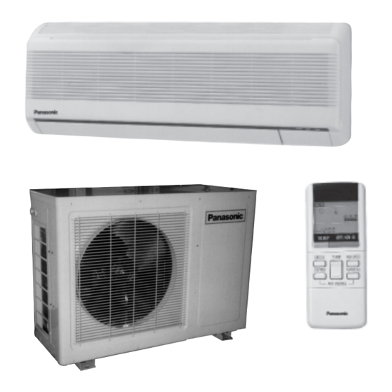
CS-MC90KE / CU-MC140KE
CS-MC90KE / CU-MC180KE
CS-MC90KE / CU-3MC200KE
Multi-Split Air Conditioner
Contents
Features .......................................................... 1
Functions ................................................... 2 - 4
Product Specifications ............................. 5 - 10
Dimensions ............................................ 11 - 12
Refrigeration Cycle Diagram ......................... 13
Block Diagram ....................................... 14 - 16
Wiring Diagram ...................................... 17 - 19
Operation Details ................................... 20 - 26
Installation Information .......................... 27 - 28
3-way Valve ........................................... 29 - 35
Servicing Information ............................. 36 - 39
Troubleshooting Guide .......................... 40 - 41
Technical Data ....................................... 42 - 44
Exploded View ............................. 45, 47, 49, 51
Replacement Parts List ............... 46, 48, 50, 52
Electronic Parts List ............................... 53 - 54
© 1997 Matsushita Industrial Corp. Sdn. Bhd.
(11969-T)
All rights reserved. Unauthorized copying and distribu-
tion is a violation of law.
ORDER NO. MAC9702008C2
Advertisement
Table of Contents
Troubleshooting

Related Manuals for Panasonic CS-MC90KE


Summary of Contents for Panasonic CS-MC90KE
-
Page 1: Table Of Contents
ORDER NO. MAC9702008C2 Service Manual Multi-Split Air Conditioner CS-MC90KE / CU-MC140KE CS-MC90KE / CU-MC180KE CS-MC90KE / CU-3MC200KE Contents Features ............1 Functions ........... 2 – 4 Product Specifications ......5 – 10 Dimensions ..........11 – 12 Refrigeration Cycle Diagram ......13 Block Diagram ........ -
Page 2: Electronic Parts List
CS-MC90KE Electronic Parts List <Model: CU-3MC200KE> CWA741165 • ELECTRONIC CONTROLLER SYMBOL DESCRIPTION & NAME PART NO. ERZC10DK471U ZENER DIODE RD24EB - T1 DIODE 1S1553 - TP3 ZENER DIODE RD12EB - T1 PHOTO ISOLATOR TLP521 - 1GB DIODE D1N60 - 4070... -
Page 3: Features
CS-MC90KE WARNING This service information is designed for experienced repair technicians only and is not designed for use by the general public. It does not contain warnings or cautions to advise non-technical individuals of potential dangers in attempting to service a product. Products powered by electricity should be serviced or repaired only by experienced professional technicians. -
Page 4: Functions
CS-MC90KE Functions Remote Control OFF / ON I TEMP. Operation OFF / ON Room Temperature Setting • Temperature Setting (16˚C to 30˚C) • Automatic Operation MODE Operation Mode Selection 2˚C lower than standard Standard • Automatic Operation Mode AUTO •... - Page 5 CS-MC90KE Functions Indoor Unit POWER I Power Switch OFF / ON Auto Restart Control • Operation is restarted after power failure AUTO at previous setting mode. OFF / ON Auto Operation Switch Anti-Freezing Control • Used when the remote control cannot be used.
-
Page 6: Functions
CS-MC90KE Functions Outdoor Unit Compressor Reverse Rotation Restart Control Protection Control (3 minutes) • To protect compressor from reverse rotation • Once the compressor stops, the compressor when there is a instantaneous power failure. and the outdoor fan motor will not start for 3 minutes. -
Page 7: Product Specifications
CS-MC90KE Product Specifications CS-MC90KE CU-MC140KE Unit × × (1 unit) 2.82 - 2.78 (2 unit) 1.81 2 - 1.79 Cooling Capacity 6,150 × 2 - 6,100 × 2 Btu/h 9,600 - 9,400 × (1 unit) 1.6 (2 unit) 1.05 Moisture Removal 2.2 ×... - Page 8 CS-MC90KE Product Specifications Unit CS-MC90KE CU-MC140KE Heat Evaporator Description Condenser Exchanger Tube material Copper Copper Aluminium Fin material Aluminium Fin Type Corrugated Fin Slot Fin Row / Stage (Plate fin configuration, forced draft) 2 × 12 1 × 20 Size (W × H × L) 600 ×...
- Page 9 CS-MC90KE Product Specifications Unit CS-MC90KE CU-MC180KE (2 units) 2.44 × 2 - 2.40 × 2 (1 unit) 2.44 - 2.40 Cooling Capacity 8,300 × 2 - 8,100 × 2 Btu/h 8,300 - 8,100 (2 units) 1.3 × 2 (1 unit) 1.5 Moisture Removal 2.75 ×...
- Page 10 CS-MC90KE Product Specifications Unit CS-MC90KE CU-MC180KE Heat Evaporator Description Condenser Exchanger Tube material Copper Copper Aluminium Fin material Aluminium Fin Type Corrugated Fin Slot Fin Row / Stage (Plate fin configuration, forced draft) 2 × 12 2 × 24 Size (W × H × L) 600 ×...
- Page 11 CS-MC90KE Product Specifications CS-MC90KE CU-3MC200KE Single Operation Single Operation Double Operation Triple Operation Unit (A, B1, B2) (B1 or B2) (B1 + B2) (A +B1 or B2) (A + B1 + B2) 2.40-2.34 2.82-2.78 3.60-3.52 5.22-5.12 6.00-5.86 Cooling Capacity Per Unit –...
-
Page 12: Product Specifications
CS-MC90KE Product Specifications Unit CS-MC90KE CU-3MC200KE Heat Evaporator Description Condenser Exchanger Tube material Copper Copper Aluminium Fin material Aluminium Fin Type Corrugated Fin Slot Fin Row / Stage (Plate fin configuration, forced draft) 2 × 12 2 × 24 600 × 252 × 25.4 756.0 ×... -
Page 13: Dimensions
CS-MC90KE Dimensions CS-MC90KE <Front View> Air intake direction Below 2100 Air outlet direction Left piping hole Right piping hole <Back View> Installation plate hooks Remote control transmitter Liquid Drain ports side side (410) (45) Relative position between the indoor unit and the installation plate <Front View>... -
Page 14: Dimensions
CS-MC90KE Dimensions CU-MC140KE CU-MC180KE CU-3MC200KE – 12 –... -
Page 15: Refrigeration Cycle Diagram
CS-MC90KE Refrigeration Cycle Diagram CS-MC90KE / CU-MC140KE 1 Evaporator LIQUID SIDE 2 Capillary tube (2) 3 3 way valve (1/4") 4 3 way valve (3/8") 5 Half union (1/4") 6 Half union (3/8") GAS SIDE Indoor Unit A 7 Switching solenoid valve (A) -
Page 16: Block Diagram
CS-MC90KE Block Diagram CS-MC90KE / CU-MC140KE – 14 –... - Page 17 CS-MC90KE Block Diagram CS-MC90KE / CU-MC180KE – 15 –...
-
Page 18: Block Diagram
CS-MC90KE Block Diagram CS-MC90KE / CU-3MC200KE – 16 –... -
Page 19: Wiring Diagram
CS-MC90KE Wiring Diagram CS-MC90KE / CU-MC140KE REMARKS: : BLUE : BROWN WIRELESS ELECTRONIC DISPLAY LAMP REMOTE CONTROLLER 220-240V, 50Hz : BLACK CONTROL (RECEIVER) POWER SUPPLY CORD : WHITE CN-DISP(W) CN-RCV (W) : RED REMOTE : ORANGE CONTROL No. : PINK... - Page 20 CS-MC90KE Wiring Diagram CS-MC90KE / CU-MC180KE REMARKS: : BLUE : BROWN WIRELESS ELECTRONIC DISPLAY LAMP : BLACK REMOTE CONTROLLER 220-240V, 50Hz CONTROL (RECEIVER) POWER SUPPLY CORD : WHITE CN-DISP(W) CN-RCV (W) : RED : ORANGE REMOTE CONTROL No. : PINK...
-
Page 21: Wiring Diagram
CS-MC90KE Wiring Diagram CS-MC90KE / CU-3MC200KE REMARKS: : BLUE : BROWN WIRELESS ELECTRONIC DISPLAY LAMP REMOTE CONTROLLER : BLACK 220-240V, 50Hz CONTROL (RECEIVER) POWER SUPPLY CORD : WHITE CN-DISP(W) CN-RCV (W) : RED : ORANGE REMOTE CONTROL No. : PINK... -
Page 22: Operation Details
CS-MC90KE Operation Details 1) Cooling Mode Operation Cooling in operation according to Remote Control setting. Time Delay Safety Control (3 minutes) • When the compressor is stopped by Power Switch, Remote Control or there is a power failure, it restarts after 3 minutes when the Power Switch, Remote Control is turned ON or the power supply is resumed. -
Page 23: Indoor Fan
CS-MC90KE Operation Details Automatic Fan Speed Mode When Automatic Fan Speed is selected at Remote Control during cooling operation. • Fan speed rotates in the range of Hi to Me. • Deodorizing Control. Indoor stop stop stop stop 40" 30"... - Page 24 CS-MC90KE Operation Details 2) Soft Dry Mode Operation • The unit starts cooling operation until the room temperature reaches the setting temperature set on the Remote Control, and then Soft Dry operation will start. • During Soft Dry operation, the Indoor Fan will operate and stop at 4-second intervals at low speed.
- Page 25 CS-MC90KE Operation Details Soft Dry Operation Time Diagram a b c d e f g h i j k l m n o p q r s t u v Intake Air Temperature Cooling ON 1.5°C Cooling OFF Set Temp.
- Page 26 CS-MC90KE Operation Details 3) Air Circulation Mode Operation • When the temperature near the ceiling reaches the setting temperature, Air Circulation Mode operation commences at low airflow volume. It stops when the temperature drops to 2°C below the setting temperature.
- Page 27 CS-MC90KE Operation Details 5) Sleep Mode Auto Operation Cooling or Soft Dry Operation 8 HOURS When you press the SLEEP Mode, the following move- 1 HOUR ment will start to avoid overcooling. • The fan speed is automatically set to Low.
-
Page 28: Operation Details
CS-MC90KE Operation Details 8) Airflow Direction Control Airflow Direction Auto-Control • When set a Airflow Direction Auto-Control with Horizontal remote control, the louver swings up and down as Upper limit shown in the diagram. 34° • The louver does not swing when the Indoor Fan Swing up and down stops during operation. -
Page 29: Installation Information
CS-MC90KE Installation Information Attached accessories Accessories part Qty. Accessories part Qty. Installation plate Clamping cover of piping Vinyl tape Installation plate fixing screw Vinyl tape Remote control Battery Air purifying filter Accessories: Flaring piping kit CZ-3F5, 7EN SELECT THE BEST LOCATION INDOOR UNIT •... -
Page 30: Installation Information
CS-MC90KE Installation Information Indoor / Outdoor unit installation diagram Length of power supply cord Piping direction Attention not to bend up drain hose (Front side) about 1.8 m about 1.1 m Right Right < < < < rear Left Left... -
Page 31: 3-Way Valve
CS-MC90KE 3-way Valve 3-way Valve (Liquid Side) 3-way Valve (Gas Side) Valve cap Flare nut Hexagonal wrench (4 mm) Flare nut Open position Open position Closed position Closed position piping piping connection connection Service port Service Service port Service port cap... -
Page 32: Evacuation Of Installation
CS-MC90KE 1 Evacuation of Installation When installing an air conditioner, be sure to evacuate the air inside the indoor unit and pipes in the following procedutre. Required tools: hexagonal wrench, adjustable wrench, The air in the indoor unit and in the piping must be torque wrench, wrench to hold the joints, purged. -
Page 33: Pumping Down
CS-MC90KE 2 Pumping down (Indoor unit) (Liquid side) (Outdoor unit) 3-way valve Close (Gas side) 3-way valve CLOSE Open Refrigerant Reclaiming Equipment CLOSE Procedure: (1) Confirm that both the 3-way valves are set to the (6) Operate the air conditioner at the cooling cycle open position. - Page 34 CS-MC90KE 3 Evacuation of Re-installation WHEN RE-INSTALLING AN AIR CONDITIONER, BE If air remains in the indoor unit and refrigeration SURE TO EVACUATE THE AIR INSIDE THE INDOOR pipes, it will affect the compressor, reduce to cooling UNIT AND PIPES in the following procedure.
- Page 35 CS-MC90KE 4 Balance refrigerant of the 3-way valves (Lack of refrigerant in the refrigeration cycle) (Indoor unit) (Liquid side) (Outdoor unit) 3-way valve Open (Gas side) 3-way valve OPEN Open Refrigerant Reclaiming Equipment OPEN Procedure: (1) Confirm that both the 3-way valves are set to the opened position.
- Page 36 CS-MC90KE 5 Evacuation (No refrigerant in the refrigeration cycle) (Indoor unit) (Liquid side) (Outdoor unit) 3-way valve Open (Gas side) 3-way valve OPEN Open Vacuum pump OPEN Procedure: (1) Connect the vacuum pump to the charge set’s centre hose. (2) Turn on the vaccuum pump to evacuate the unit.
-
Page 37: Way Valve
CS-MC90KE 6 Gas charging (After Evacuation) (Indoor unit) (Liquid side) (Outdoor unit) 3-way valve Open (Gas side) CLOSE 3-way valve Check valve Open Charging cylinder OPEN Procedure: (1) Connect the charge hose to the charging cylinder. Connect the charge hose which was disconnected from the vacuum pump to the valve at the bottom of the cylinder. -
Page 38: Servicing Information
CS-MC90KE Servicing Information Sensors Earth Wire Connector Inspection points for the Indoor Electronic Control- Electronic Controller 1. The Electronic Controller, a signal Receiver and an Indicator can be seen by removing the Front Grille Electronic and Control Board Cover, as shown in the Fig. 1. - Page 39 CS-MC90KE Servicing Information Fan Motor securing screw 3. Remove the Fan Motor Loosen the Fan Motor securing screw at the junction with Cross Flow Fan. (Fig. 5) Fig. 5 Remove the particular piece and the Fan Motor can be taken off as shown in Fig. 6 and 7.
- Page 40 CS-MC90KE Servicing Information Cross Flow Fan Removal Procedure 1. Remove the Indoor Fan Motor. (Refer to the removal procedure of the Indoor Fan Motor.) (Fig. 9) Fan Motor Fig. 9 2. Remove the Air Discharge Grille by taking off the...
-
Page 41: Servicing Information
CS-MC90KE Servicing Information • Auto/Manual control switch for solenoid control valve 1. AUTO operation When the AUTO/MANUAL control switch is turned to the “AUTO” position, the normal operation of solenoid control valve will be performed. (The open and close of the solenoid controlled valve is depend on the controller.) -
Page 42: Troubleshooting Guide
CS-MC90KE Troubleshooting Guide Refrigeration cycle system In order to diagnose malfunctions, make sure that Normal Pressure and Outlet Air Temperature (Standard) there are no electrical problems before inspect- Gas pressure Outlet air ing the refrigeration cycle. Such problems include temperature... -
Page 43: Troubleshooting Guide
CS-MC90KE Troubleshooting Guide 1. Relationship between the condition of the air conditioner and pressure and electric current Cooling Mode Condition of the air High Pressure Electric current during operation Low Pressure conditioner Insufficient refrigerant (gas leakage) Clogged capillary tube or Strainer... -
Page 44: Technical Data
CS-MC90KE Technical Data L L L L L Thermostat characteristics CS-MC90KE • Cooling (°C) COMP. ON COMP. OFF = Set temperature diff. 1.5°C (°C) Thermostat setting (remote control) • Soft Dry (°C) Cooling ON Cooling OFF = Set Temperature, Soft Dry ON Soft Dry OFF Diff. - Page 45 CS-MC90KE Technical Data L L L L L Operation characteristics [Conditions]: Room temperature: 27/19°C Cooling operation: At High Fan Piping length: 5 m At 220V • CS-MC90KE/CU-MC140KE : 1 unit operation : 2 units operation Outside Air Temperature (°C) •...
-
Page 46: Technical Data
CS-MC90KE Technical Data Operation characteristics [Conditions]: Room temperature: 27/19°C Cooling operation: At High Fan Piping length: 5 m At 220V • CS-MC90KE/CU-3MC200KE 1 Unit Operation 3 Units Operation : UNIT A : UNIT A : UNIT B1 OR B2 : UNIT B1 AND B2 Outside Air Temperature (°C) -
Page 47: Exploded View
CS-MC90KE Exploded View CS-MC90KE " & < > – 45 –... - Page 48 CS-MC90KE Exploded View CU-MC140KE < > & " – 47 –...
- Page 49 CS-MC90KE Exploded View CU-MC180KE < & > > " – 49 –...
- Page 50 CS-MC90KE Exploded View CU-3MC200KE > < " " & " – 51 –...
-
Page 51: Replacement Parts List
CS-MC90KE Replacement Parts List <Model: CS-MC90KE> DESCRIPTION & NAME CS-MC90KE REMARKS CHASSY COMPLETE CWD50C202 FAN MOTOR CWA92232 CROSS FLOW FAN COMPLETE CWH02C053 SCREW – CROSS FLOW FAN CWH4580304 BEARING ASS’Y CWH64K007 EVAPORATOR CWB30C178 TUBE ASS’Y COMPLETE CWT01C237 FLARE NUT (1/4") CWH6002140 FLARE NUT (3/8") - Page 52 CS-MC90KE Replacement Parts List <Model: CU-MC140KE> DESCRIPTION & NAME Q’TY CU-MC140KE REMARKS BASE ASS'Y CWD50K573A SOUND PROOF COVER CWH15066 FAN MOTOR BRACKET CWD54168 CONDENSER CWB32C142 FAN MOTOR CWA95354 PROPELLER FAN CWH00022 COMPRESSOR 2PS192D2AA02 3-WAY VALVE (LIQUID SIDE) CWB01383 3-WAY VALVE (GAS SIDE)
- Page 53 CS-MC90KE Replacement Parts List <Model: CU-MC180KE> DESCRIPTION & NAME Q’TY CU-MC180KE REMARKS BASE ASS'Y CWD50K572A CWD31094A AIR GUIDER FOR P.F. SOUND PROOF COVER CWH15071 FAN MOTOR BRACKET CWD54179 CONDENSER CWB32487 FAN MOTOR CWA95269 CWH00023 PROPELLER FAN COMPRESSOR 2PS134D2AA01 3-WAY VALVE (LIQUID SIDE)
- Page 54 CS-MC90KE Replacement Parts List <Model: CU-3MC200KE> CU-3MC200KE DESCRIPTION & NAME REMARKS BASE FAN ASS'Y CWD50K572A COMPRESSOR 2PS193D2AA01 AIR GUIDER CWD31094A SOUND PROOF COVER CWH15071 FAN MOTOR BRACKET CWD54179 CONDENSOR CWB32C141 FAN MOTOR CWA95358 PROPELLER FAN CWH00023 COMPRESSOR 2PS134D2AA01 3-WAY VALVE (LIQUID SIDE)
- Page 55 CS-MC90KE Electronic Parts List <Model: CS-MC90KE> CWA74813 • ELECTRONIC CONTROLLER (MAIN) SYMBOL DESCRIPTION & NAME PART NO. SOUND GENERATOR A48004 C–FM SH CAPACITOR A31496 DIODE A54RA15–01V3 DIODE A54CS1VB20E FUSE FUSE XBA2C31TR0 INTEGRATED CIRCUIT A52D0001W013 A52C040 INTEGRATED CIRCUIT INTEGRATED CIRCUIT A52MPA2003C...
- Page 56 CS-MC90KE Electronic Parts List <Model: CU-MC140KE, CU-3MC200KE> CWA741123, CWA741165 • ELECTRONIC CONTROLLER DESCRIPTION & NAME CWA741123 CWA741165 SYMBOL ← DIODE A54RA15 - 01V3 DIODE – A54RA15 - 01V3 ← DIODE A54MA165TA5 ← TRANSISTOR A55C1741ASTR TRANSISTOR – A55C1741ASTR ← TRANSISTOR A55DTC113ZST Q3, Q4, Q5 ←...