Panasonic CS-MZ16TKE Service Manual
Hide thumbs
Also See for CS-MZ16TKE:
- Operating instructions manual (92 pages) ,
- Service manual (104 pages)
Table of Contents
Advertisement
Quick Links
Please file and use this manual together with the service manual for Model No. CU-2E12SBE CU-2E15SBE CU-2E18SBE
CU-3E23SBE, Order No. PAPAMY1601015CE, CU-3E18PBE CU-4E23PBE, Order No. PAPAMY1301048CE and CU-4E27PBE
CU-5E34PBE, Order No. PAPAMY1303046CE.
This service information is designed for experienced repair technicians only and is not designed for use by the general public.
It does not contain warnings or cautions to advise non-technical individuals of potential dangers in attempting to service a product.
Products powered by electricity should be serviced or repaired only by experienced professional technicians. Any attempt to service
or repair the products dealt with in this service information by anyone else could result in serious injury or death.
There are special components used in this equipment which are important for safety. These parts are marked by
Diagrams, Circuit Board Diagrams, Exploded Views and Replacement Parts List. It is essential that these critical parts should be replaced
with manufacturer's specified parts to prevent shock, fire or other hazards. Do not modify the original design without permission of
manufacturer.
In order to avoid frostbite, be assured of no refrigerant leakage during the installation or repairing of refrigerant circuit.
R32 REFRIGERANT
– This Air Conditioner contains and operates with refrigerant R32.
THIS PRODUCT MUST ONLY BE INSTALLED OR SERVICED BY QUALIFIED PERSONNEL.
Refer to Commonwealth, State, Territory and local legislation, regulations, codes, installation & operation manuals, before the
installation, maintenance and/or service of this product.
WARNING
IMPORTANT SAFETY NOTICE
PRECAUTION OF LOW TEMPERATURE
CAUTION
Order No: PAPAMY1702034CE
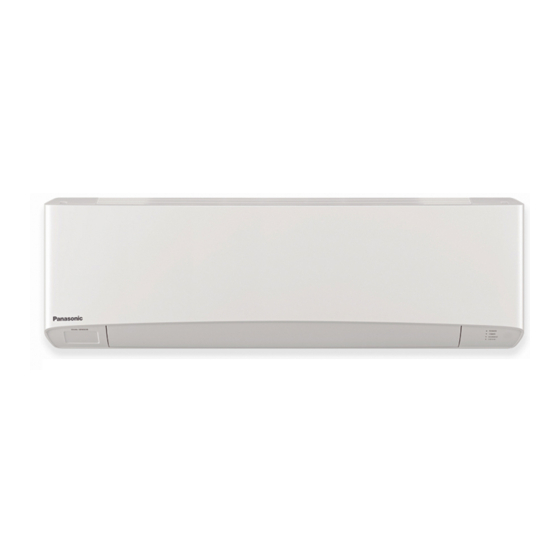
Indoor Unit
CS-MZ16TKE
Destination
Europe
Turkey
in the Schematic
© Panasonic Corporation 2017.
Advertisement
Table of Contents

Subscribe to Our Youtube Channel
Related Manuals for Panasonic CS-MZ16TKE


Summary of Contents for Panasonic CS-MZ16TKE
- Page 1 – This Air Conditioner contains and operates with refrigerant R32. THIS PRODUCT MUST ONLY BE INSTALLED OR SERVICED BY QUALIFIED PERSONNEL. Refer to Commonwealth, State, Territory and local legislation, regulations, codes, installation & operation manuals, before the installation, maintenance and/or service of this product. © Panasonic Corporation 2017.
-
Page 2: Table Of Contents
TABLE OF CONTENTS PAGE PAGE Safety Precautions ..........3 12.3 Heating Operation ........66 12.4 Automatic Operation ........67 Precaution for Using R32 Refrigerant ....6 12.5 Indoor Fan Motor Operation .......67 12.6 Powerful Mode Operation ......67 Specifications ........... -
Page 3: Safety Precautions
1. Safety Precautions Read the following “SAFETY PRECAUTIONS” carefully before perform any servicing. Electrical work must be installed or serviced by a licensed electrician. Be sure to use the correct rating of the power plug and main circuit for the model installed. ... - Page 4 WARNING Do not perform flare connection inside a building or dwelling or room, when joining the heat exchanger of indoor unit with interconnecting piping. Refrigerant connection inside a building or dwelling or room must be made by brazing or welding. Joint connection of indoor unit by flaring method can only be made at outdoor or at outside of a building or dwelling or room.
- Page 5 CAUTION Do not touch the sharp aluminium fin, sharp parts may cause injury. Carry out drainage piping as mentioned in installation instructions. If drainage is not perfect, water may enter the room and damage the furniture. Select an installation location which is easy for maintenance. Incorrect installation, service or repair of this air conditioner may increase the risk of rupture and this may result in loss damage or injury and/or property.
-
Page 6: Precaution For Using R32 Refrigerant
2. Precaution for Using R32 Refrigerant The basic installation work procedures are the same as conventional refrigerant (R410A, R22) models. However, pay careful attention to the following points: WARNING Since the working pressure is higher than that of refrigerant R22 models, some of the piping and installation and service tools are special. - Page 7 CAUTION 2-5. No ignition sources No person carrying out work in relation to a refrigeration system which involves exposing any pipe work that contains or has contained flammable refrigerant shall use any sources of ignition in such a manner that it may lead to the risk of fire or explosion. He/She must not be smoking when carrying out such work.
- Page 8 CAUTION Leak detection methods Electronic leak detectors shall be used to detect flammable refrigerants, but the sensitivity may not be adequate, or may need re- calibration. (Detection equipment shall be calibrated in a refrigerant-free area.) Ensure that the detector is not a potential source of ignition and is suitable for the refrigerant used. ...
- Page 9 CAUTION Labelling Equipment shall be labelled stating that it has been de-commissioned and emptied of refrigerant. The label shall be dated and signed. Ensure that there are labels on the equipment stating the equipment contains flammable refrigerant. Recovery ...
-
Page 10: Specifications
3. Specifications Model Indoor CS-MZ16TKE Performance Test Condition EUROVENT Phase, Hz Single, 50 Power Supply Min. Mid. Max. 1.30 1.60 2.30 Capacity BTU/h 4430 5460 7840 Running Current – 2.00 – Input Power Annual Consumption – – 5.20 4.00 3.59... - Page 11 Model Indoor CS-MZ16TKE Height (I/D) mm (inch) 295 (11-5/8) Dimension Width (I/D) mm (inch) 919 (36-3/16) Depth (I/D) mm (inch) 194 (7-21/32) Weight Net (I/D) kg (lb) 9 (20) Pipe Diameter Piping mm (inch) 6.35 (1/4) / 9.52 (3/8) (Liquid / Gas) Inner Diameter 16.7...
- Page 12 A single outdoor unit enables air conditioning of up to two separate rooms for CU-2E12SBE, CU-2E15SBE, CU-2E18SBE. A single outdoor unit enables air conditioning of up to three separate rooms for CU-3E23SBE, CU-3E18PBE. CONNECTABLE INDOOR UNIT CU-2E12SBE CU-2E15SBE CU-2E18SBE CU-3E23SBE CU-3E18PBE ROOM 1.6kW CS-MZ16TKE ● ● ● ● ● ● ● ● ● ●...
- Page 13 A single outdoor unit enables air conditioning of up to four separate rooms for CU-4E23PBE, CU-4E27PBE. A single outdoor unit enables air conditioning of up to five separate rooms for CU-5E34PBE. CONNECTABLE INDOOR UNIT CU-4E23PBE CU-4E27PBE CU-5E34PBE ROOM 1.6kW CS-MZ16TKE ● ● ● ● ● ● ●...
-
Page 14: Location Of Controls And Components
4. Location of Controls and Components Indoor Unit Front panel Aluminium fin Auto OFF/ON button Use when remote control is misplaced or a malfunction occurs. Horizontal airflow direction louver Do not adjust by hand. Human activity sensor Sunlight Sensor and Vertical airflow direction louver Remote Control Receiver Do not adjust by hand. -
Page 15: Dimensions
5. Dimensions Indoor Unit <Top View> <Side View> <Front View> <Side View> Air intake direction 2 ±0.5 2 ±0.5 Left piping Air outlet Right piping hole direction hole <Remote Control> <Bottom View> Gas side <Rear View> Liquid side <Remote Control Holder> (41-61) Relative position between the indoor unit and the installation plate <Front View>... -
Page 16: Wiring Connection Diagram
6. Wiring Connection Diagram Indoor Unit... -
Page 17: Electronic Circuit Diagram
7. Electronic Circuit Diagram Indoor Unit ELECTRONIC CONTROLLER (SUB) CN-NANO HIGH VOLTAGE BLUE NANOE WHITE WHITE POWER SUPPLY CN-DATA2 GENERATOR WHITE W W W W CN-DATA2 YELLOW AC306 TERMINAL SW01 (BLK) BOARD *IC06 FUSE301 AC303 T.3.15A L250V (WHT) NOISE FILTER CIRCUIT UP DOWN LOUVER MOTOR... -
Page 18: Printed Circuit Board
8. Printed Circuit Board Indoor Unit 8.1.1 Main Printed Circuit Board AC303 CN-FM CN-DATA1 CN-CNT CN-STM1 CN-STM2 CN-STM3 CN-DATA2 CN-DISP CN-RMT CN-RCV CN-TH CN-MSENS JP1 (Random Auto Restart enable/disable) - Page 19 8.1.2 Indicator Printed Circuit Board LED205 LED203 LED201 LED206 LED204 LED202 CN-DISP 8.1.3 Receiver Printed Circuit Board CN-RCV 8.1.4 High Voltage Power Supply Printed Circuit Board...
- Page 20 8.1.5 Sub Printed Circuit Board AC302 ACL501 ACN501 CN-DATA1 AC306 ACN502 CN-NANO CN-DATA2 8.1.6 Human Activity Sensor Printed Circuit Board 8.1.7 Comparator Printed Circuit Board CN-SENS2 CN-SENS1 CN-MSENS...
-
Page 21: Installation Instruction
9. Installation Instruction Select the Best Location 9.1.2 Indoor Unit Installation Diagram 9.1.1 Indoor Unit Piping direction Attention not to bend WARNING (Front side) up drain hose Do not install the unit in excessive oil fume area Right Flare connection only at Right such as kitchen, workshop and etc. -
Page 22: Indoor Unit
Indoor Unit 9.2.1 How to fix the Installation Plate The mounting wall shall be strong and solid enough to prevent it from vibration. The mounting wall shall be strong and solid enough to prevent it from vibration. Ceiling Wall Wall More than 1 More than 1 More... - Page 23 9.2.3 Indoor Unit Installation Do not turn over the unit without it’s shock absorber during pull out the piping. It may cause intake grille damage. Use shock absorber during pull out the piping to protect the intake grille from damage. Piping Piping Intake grille...
- Page 24 Right Rear piping Tape it with piping in a position as mentioned in Fig. below. Piping Cover for the Cover for the Cover for left bottom piping Drain the right piping hose Cover for the piping bottom piping Cover for piping How to keep the cover In case of the cover is cut, keep the cover at the rear of chassis as...
- Page 25 Exchange the drain hose and the cap Rear view for left piping installation Connection cable Piping More than 950 mm Drain hose Drain hose Connection cable Drain cap Drain hose Adjust the piping Sleeve for piping hole slightly downwards. • •...
- Page 26 9.2.4 Connect the Cable to the Indoor Unit The inside and outside connection cable can be connected without removing the front grille. Connection cable between indoor unit and outdoor unit shall be approved polychloroprene sheathed 4 × 1.5 flexible cord, type designation 60245 IEC 57 or heavier cord. Do not use joint connection cable. Replace the wire if the existing wire (from concealed wiring, or otherwise) is too short.
- Page 27 RISK OF FIRE JOINING OF WIRES MAY CAUSE OVERHEATING AND WARNING FIRE. Do not joint wires Use complete wire without joining. Use approved socket and plug with earth pin. Wire connection in this area must follow to national wiring rules. 9.2.4.2 Cutting and Flaring the Piping Please cut using pipe cutter and then remove the burrs.
-
Page 28: Installation And Servicing Air Conditioner Using R32
10. Installation and Servicing Air Conditioner using R32 10.1 About R32 Refrigerant For air conditioning refrigerants such as R410A, the refrigerants were collected back in order to prevent their air dissipation, to curbe the global warming impact, in case they were released into the atmosphere. In the “4th Environmental Basic Plan”, 80% reduction of greenhouse gas emissions by 2050 is required, and due to this requirement, further reduction in the emission of high greenhouse effect gas, such as CFCs, is required. - Page 29 2. Characteristic of Pressure As shown in Table 2, R32 does not have much difference in vapor pressure at the same refrigerant temperature comparing to R410A, but comparing to R22, it is higher at 1.6 times more. Thus, the same as in case of R410A, it is necessary to do installation and service using high-pressure tools and components.
-
Page 30: Refrigerant Piping Installation • Tools Used In Services
10.3 Refrigerant piping installation • Tools used in services 10.3.1 Required Tools R32 refrigerant air conditioners use the common parts as R410A air conditioners for two-way valves and three-way valves (diameters of service ports); thus, they maintain commonality in the maintenance of the compressive strength, the size of pipe flaring, and the size of flare nuts as R410A. - Page 31 3. Torque wrenches (diameters 1/2, 5/8) Manifold gauges / Charging hoses In order to strengthen the compressive strength, the diameters of wrenches change depending on the flare nut sizes. Torque wrenches Differences in charging hoses Differences in torque wrenches (common R410A) Normal 5.1 MPa 3.4 MPa...
- Page 32 7. HFC refrigerant_Electric gas leakage tester 9. Refrigerant cylinders R32 refrigerant is often used for other mixed Refrigerant cylinders for R410A are painted in pink, refrigerant (R410A, R404A, R407C etc.). Therefore, and the ones for R32 are painted in other colors that the usage of existing HFC detectors is possible, but in might subject to change according to the international order to detect more accurately, we recommend to...
- Page 33 11. Tools used for refrigerant piping installations and services Tools for R410A Common with R32 Possibility of usage for R22 ○ ○ Pipe cutters, reamers or scrapers ○ ○ Flare tools (clutch type) ○ ○ Torque wrench (1/4, 3/8) ○ ×...
-
Page 34: New Installation, Relocation, Repairing Of Refrigerant Cycle System The Procedures
10.4 New installation, Relocation, Repairing of Refrigerant Cycle System The Procedures Relocation Repairing refrigerant cycle Installation Indoor / outdoor units and piping Pump down Refrigerant recovery • Displacing pipes and wires, and displacing indoor / outdoor units Prevention of impurity •... -
Page 35: Piping Installation Of R32
10.5 Piping installation of R32 10.5.1 Pipe materials used and flaring Copper pipes are used for refrigerant piping. Pipes Pipe thickness which comply with JIS Regulations need to be used. Room air conditioners which use R410A and R32 O and OL materials Thickness (mm) have higher pressure;... -
Page 36: Installation, Relocation, And Service
10.6 Installation, Relocation, and Service 10.6.1 Air purge and gas leak test for new installation (using new refrigerant pipes) using vacuum pump (From the point of view of global environment protection, do not release CFCs into the atmosphere during installation work) 1. - Page 37 10.6.2 Process of refrigerant recovery 1. Connect the center charging hose of manifold gauge to the in-let side of recovery device. 2. Connect the valves of the discharge side of recovery device and liquid side of refrigerant cylinder with red hose (charging hose).
- Page 38 10.6.3 Relocation 1. Removing the air conditioning unit a) Recovery of outdoor unit refrigerant by pumping down Press “forced cooling button” (as a general rule, since 1998 the name of cooling testing button is changed, and this name is unified within the air conditioning industry), and then you are able to start cooling operation in which the room temperature is low, and you can recover the refrigerant from the outdoor unit.
- Page 39 10.6.6 Re-insertion of refrigerant in service When re-insertion is needed, follow the procedures to ensure the insertion of new refrigerant at correct amount. 1. Attach charging hose (blue) to the service port of the outdoor unit. 2. Attach charging hose (red) to the vacuum pump. Fully open the 2-way and 3-way valves. 3.
-
Page 40: Repairing Of Refrigerant Cycle / Brazing Point
10.7 Repairing of refrigerant cycle / Brazing point 10.7.1 Preparation for repairing of refrigerant cycle / brazing Brazing which is a technique needed for repairing refrigerant cycle requires advanced technique and experience, and this brazing procedure can only be performed by the workers who completed “Gas Welding Skill Training” regulated by the Occupational Safety and Health Act, and went through the training programs of refrigerant operations. - Page 41 2. Cylinder without adjustment valve side gauge pressure is adjusted by the adjuster. Check the both side valves of the torch and open the cylinder valve to check the remaining refrigerant in the cylinder. Caution: Do not attach oil component on the connection port of the adjuster. Especially, use an oxygen cylinder adjuster which is no oil substance type.
- Page 42 10.7.5 Types of flame Types of flame change based on the proportion of propane and oxygen. [Neutral Flame] Perform brazing with this flame (This is a flame when oxygen and propane are mixed at proper proportion, and has lesser effect on the brazed metals) White core flame 10 ~ 15 mm...
- Page 43 10.7.7 Selection of brazing material Use BAg brazing material (silver solder) to increase the welding performance. Tensile strength Composition of ingredients (%) Temperature (°C) Characteristics (Reference) Category Standard Brazing Base Number applications Solidus Liquidus Kgf•cm temp material Liquidity is good at low temperature, 49.0 14.5...
- Page 44 10.7.10 Checking of brazing (insert) points 1. No impurity on the brazing point Gap 0.025 ~ 0.05 mm If dirt or oil is attached on the brazing point, the brazing filler metal does not reach to junction, and Inner diameter ø6.45 it may cause poor welding.
- Page 45 (Reference) Melting temperature of copper • • • • • • • Approx. 1083°C Maximum temperature obtained in propane and oxygen • • • • • • • Approx. 1083°C The important point is to heat the bonding part uniformly within a short period of time until reaching to the brazing temperature in the following manner.
-
Page 46: Reference> Analysis Method For No Error Code, No Cooling / No Warming
10.8 <Reference> Analysis method for no error code, no cooling / no warming 10.8.1 Preparation for appropriate diagnosis In order to obtain appropriate operation characteristics, minimum 15 minutes or more operation time [testing operation (rated operation)] is required. 1. Method of rated operation (rated operation) For the models which have two buttons of “emergency operation and forced cooling operation”, press forced cooling button once. - Page 47 1. Measuring temperature 1) Indoor unit suction temperature, release temperature, temperature difference, → Measure by thermometer 2) 2-way valve pipe temperature in cooling mode is low temperature (benchmark:5 ~ 10°C), in heating mode is medium temperature (benchmark:25 ~ 35°C). 3) 3-way valve pipe temperature in cooling mode is low temperature (benchmark:7 ~ 15°C) in heating mode is high temperature (benchmark:38 ~ 50°C).
-
Page 48: Operation Control
11. Operation Control 11.1 Basic Function Inverter control, which equipped with a microcomputer in determining the most suitable operating mode as time passes, automatically adjusts output power for maximum comfort always. In order to achieve the suitable operating mode, the microcomputer maintains the set temperature by measuring the temperature of the environment and performing temperature shifting. -
Page 49: Indoor Fan Motor Operation
11.1.5 Automatic Operation This mode can be set using remote control and the operation is decided by remote control setting temperature, remote control operation mode and indoor intake air temperature. During operation mode judgment, indoor fan motor (with speed of Lo-) is running for 30 seconds to detect the indoor intake air temperature. - Page 50 [Heating] According to indoor pipe temperature, automatic heating fan speed is determined as follows. B. Feedback control Immediately after the fan motor started, feedback control is performed once every second. During fan motor on, if fan motor feedback ≥ 2550 rpm or < 50 rpm continue for 10 seconds, then fan motor error counter increase, fan motor is then stop and restart.
-
Page 51: Airflow Direction
11.3 Airflow Direction There are two types of airflow, vertical airflow (directed by horizontal vane) and horizontal airflow (directed by vertical vanes). Control of airflow direction can be automatic (angles of direction is determined by operation mode, heat exchanger temperature and intake air temperature) and manual (angles of direction can be adjusted using remote control). - Page 52 Side View (Inner Vane) Reference point 128º Step 1 Stopper Step 2 Step 3 Closed Position Step 4 Step 5 Side View (Outer Vane) Closed Stopper Position 156º Reference point Step 1 Step 2 Step 3 Step 4 Step 5 Figure 2 * The horizontal vane angle tolerance is within +/- 5 degree.
- Page 53 11.3.2 Horizontal Airflow Automatic horizontal airflow direction can be set using remote control; the vane swings left and right within the angles as stated below. For heating mode operation, the angle of the vane depends on the indoor heat exchanger temperature as Figure 1 below.
-
Page 54: Quiet Operation (Cooling Mode/Cooling Area Of Dry Mode)
11.4 Quiet Operation (Cooling Mode/Cooling Area of Dry Mode) Purpose To provide quiet cooling operation compare to normal operation. Control condition Quiet operation start condition When “POWERFUL/QUIET” button at remote control is pressed twice. QUIET will be shown on remote control display. Quiet operation stop condition ... -
Page 55: Timer Control
11.7 Timer Control There are 2 sets of ON and OFF timer available to turn the unit ON or OFF at different preset time. If more than one timer had been set, the upcoming timer will be displayed and will activate in sequence. 11.7.1 ON Timer Control ... -
Page 56: Indication Panel
11.10 Indication Panel POWER TIMER nanoe ECONAVI Color White White White White Light ON Operation ON Timer Setting ON nanoe ON ECONAVI ON Light OFF Operation OFF Timer Setting OFF nanoe OFF ECONAVI OFF Note: If POWER LED is blinking, the possible operation of the unit are Hot Start, during Deice operation, operation mode judgment, or ON timer sampling. - Page 57 Remote Control Receiving Sound Normal Operation nanoe Operation : Beep nanoe Operation Normal Operation : Beep Stop nanoe individual Operation : Beep nanoe individual Operation Stop : Long Beep Power failure During nanoe individual operation, if power failure occurs, after power resumes, nanoe individual operation resumes immediately.
-
Page 58: Econavi Operation
nanoe Discharge Abnormality Abnormal detection condition After 30 minutes nanoe power ON, abnormal signal is being detected continuously for 5s. Action after abnormal detection condition fulfilled Abnormal discharge counter +1, nanoe power OFF for 30 minutes and then restart. When abnormal discharge counter ≥... - Page 59 11.12.1 Human Activity Sensor Area of human availability, activity level and absent is judged based on pulses by using 2 infrared sensors. The internal setting temperature shift, fan speed and horizontal airflow direction are adjusted in order to provide comfort environment while maintain the energy saving level.
- Page 60 11.12.1.4 Human Position Analysis According to Area of Living, frequency of activity and indoor unit intake temperature, the system will analyze the human position away from the indoor unit. 11.12.1.5 Target Area and Position Judgment The system will judge the indoor unit installation position according to human activity Non-Living Area: Non-Living Area at Position A –...
- Page 61 11.12.1.8 Setting Temperature and Fan Speed Shift ECONAVI ; Detecting human presence and activity, the unit controls room temperature to save energy. Human Mode Low activity Normal activity High activity Absent +2°C COOL/DRY +1°C temperature HEAT -2°C -2°C 11.12.1.9 Rhythmic Temperature Wave Operation ...
- Page 62 11.12.1.10 ECONAVI Demo Mode To enable ECO DEMO mode, during unit is OFF (power standby): Remote control normal mode Press continously for 5s Transmit ECO demo code and after 30 seconds return to normal mode. Transmit sunlight sensor check code and after 30 seconds return to normal mode.
- Page 63 11.12.1.12 Human Activity Sensor Check Mode To enable Human Activity sensor abnormality check mode, during ECONAVI operation ON: Remote control normal mode Press continously for 5s Transmit ECO demo code and after 30 seconds return to normal mode. Transmit sunlight sensor check code and after 30 seconds return to normal mode.
- Page 64 11.12.2.2 Judge Sunlight Intensity Based on sunlight sensor output voltage, the sunlight intensity value will be computed and logged to sunlight intensity database. The sunlight sensor sensitivity could be adjusted: Remote control normal mode Press & release Press to choose No.2 Sensitivity Level 1: Less sensitive to sunlight intensity Default: (Battery insert) Sensitivity Level 3: Default sensitive level...
- Page 65 11.12.2.5 Sunlight Sensor Check Mode To enable sunlight sensor check mode, during unit is OFF (power standby): Remote control normal mode Press continously for 5s Transmit ECO demo code and after 30 seconds return to normal mode. Transmit sunlight sensor check code and after 30 seconds return to normal mode.
-
Page 66: Operation Control (For Multi Split Connection)
12. Operation Control (For Multi Split Connection) During multi split connection, indoor unit’s operation controls are same with single split connection unless specified in this chapter. 12.1 Cooling operation 12.1.1 Thermostat control Capability supply to indoor unit is OFF (Expansion valve closed) when Intake Air Temperature — Internal setting temperature <... -
Page 67: Automatic Operation
12.4 Automatic Operation This mode can be set using remote control and the operation is decided by remote control setting temperature, remote control operation mode, indoor intake and outdoor air temperature. During operation mode judgment, indoor fan motor (with speed of -Lo) and outdoor fan motor are running for 30 seconds to detect the indoor intake and outdoor air temperature. -
Page 68: Servicing Mode
13. Servicing Mode 13.1 Auto OFF/ON Button AUTO OPERATION MODE The Auto operation will be activated immediately once the Auto OFF/ON button is pressed. This operation can be used to operate air conditioner with limited function if remote control is misplaced or malfunction. TEST RUN OPERATION (FOR PUMP DOWN/SERVICING PURPOSE) The Test Run operation will be activated if the Auto OFF/ON button is pressed continuously for more than 5 seconds. -
Page 69: Remote Control Button
REMOTE CONTROL RECEIVING SOUND OFF/ON MODE The Remote Control Receiving Sound OFF/ON Mode will be activated if the Auto OFF/ON button is pressed continuously for more than 16 seconds (4 “beep” sounds will occur at 16th seconds to identify the Remote Control Receiving Sound Off/On Mode is in standby condition) and press “AC Reset”... - Page 70 13.2.6 Special Setting mode LCD display area: Special setting display area (highlighted in color) Function Options (If any) Cannot enter this special setting mode under the following conditions: 1 Operation ON. 2 Under [Real/ON/OFF] time setting mode. To enter zone 1 area: Normal display Enter Zone1 mode...
- Page 71 Function & Options list: Note: The functions described in the table may not be applicable to the model and may subject to change without further notice. Function Options Remark Name Remote control number selection A, B, C, D Solar radiation sensitivity level adjustment 1, 2, 3, 4, 5 [iAUTO-X/iAUTO/iCOMF, Cool &...
-
Page 72: Troubleshooting Guide
14. Troubleshooting Guide 14.1 Refrigeration Cycle System In order to diagnose malfunctions, make sure that there are no Normal Pressure and Outlet Air Temperature (Standard) electrical problems before inspecting the refrigeration cycle. Gas Pressure Outlet air Temperature Such problems include insufficient insulation, problem with the (kg/cm (°C) power source, malfunction of a compressor and a fan. - Page 73 14.1.1 Relationship Between the Condition of the Air Conditioner and Pressure and Electric Current Cooling Mode Heating Mode Condition of the Electric current Electric current air conditioner Low Pressure High Pressure Low Pressure High Pressure during operation during operation Insufficient refrigerant ...
-
Page 74: Breakdown Self Diagnosis Function
14.2 Breakdown Self Diagnosis Function 14.2.1 Self Diagnosis Function (Three Digits Alphanumeric Code) Every press of the button (up or down) will Once abnormality has occurred during operation, increase abnormality numbers and transmit the unit will stop its operation, and Timer LED abnormality code signal to the main unit. -
Page 75: Error Codes Table
14.3 Error Codes Table Diagnosis Abnormality / Abnormality Protection Problem Check location display Protection control Judgment Operation No memory of failure — Normal operation — — Indoor fan only Indoor/outdoor wire terminal Indoor/outdoor operation can Indoor/outdoor After operation for ... - Page 76 Diagnosis Abnormality / Abnormality Protection Problem Check location display Protection control Judgment Operation Check indoor/outdoor Wrong wiring and connection wire and connection Abnormal wiring or — — connecting pipe, expansion pipe piping connection valve abnormality Expansion valve and lead wire and connector ...
-
Page 77: Self-Diagnosis Method
14.4 Self-diagnosis Method 14.4.1 H11 (Indoor/Outdoor Abnormal Communication) Malfunction Decision Conditions During startup and operation of cooling and heating, the data received from outdoor unit in indoor unit signal transmission is checked whether it is normal. Malfunction Caused Faulty indoor unit PCB. - Page 78 14.4.2 H12 (Indoor/Outdoor Capacity Rank Mismatched) Malfunction Decision Conditions During startup, error code appears when different types of indoor and outdoor units are interconnected. Malfunction Caused Wrong models interconnected. Wrong indoor unit or outdoor unit PCBs mounted. ...
- Page 79 14.4.3 H14 (Indoor Intake Air Temperature Sensor Abnormality) Malfunction Decision Conditions During startup and operation of cooling and heating, the temperatures detected by the indoor intake air temperature sensor are used to determine sensor errors. Malfunction Caused Faulty connector connection. ...
- Page 80 14.4.4 H15 (Compressor Temperature Sensor Abnormality) Malfunction Decision Conditions During startup and operation of cooling and heating, the temperatures detected by the outdoor compressor temperature sensor are used to determine sensor errors. Malfunction Caused Faulty connector connection. Faulty sensor.
- Page 81 14.4.5 H16 (Outdoor Current Transformer) Malfunction Decision Conditions An input current, detected by Current Transformer CT, is below threshold value when the compressor is operating at certain frequency value for 3 minutes. Malfunction Caused Lack of gas Broken CT (current transformer) ...
- Page 82 14.4.6 H19 (Indoor Fan Motor – DC Motor Mechanism Locked) Malfunction Decision Conditions The rotation speed detected by the Hall IC during fan motor operation is used to determine abnormal fan motor (feedback of rotation > 2550 rpm or < 50 rpm) Malfunction Caused ...
- Page 83 14.4.7 H23 (Indoor Pipe Temperature Sensor Abnormality) Malfunction Decision Conditions During startup and operation of cooling and heating, the temperatures detected by the indoor heat exchanger temperature sensor are used to determine sensor errors. Malfunction Caused Faulty connector connection. ...
- Page 84 14.4.8 H27 (Outdoor Air Temperature Sensor Abnormality) Malfunction Decision Conditions During startup and operation of cooling and heating, the temperatures detected by the outdoor air temperature sensor are used to determine sensor errors. Malfunction Caused Faulty connector connection. ...
- Page 85 14.4.9 H28 (Outdoor Pipe Temperature Sensor Abnormality) Malfunction Decision Conditions During startup and operation of cooling and heating, the temperatures detected by the outdoor pipe temperature sensor are used to determine sensor errors. Malfunction Caused Faulty connector connection. ...
- Page 86 14.4.10 H30 (Compressor Discharge Temperature Sensor Abnormality) Malfunction Decision Conditions During startup and operation of cooling and heating, the temperatures detected by the outdoor discharge pipe temperature sensor are used to determine sensor errors. Malfunction Caused Faulty connector connection. ...
- Page 87 14.4.11 H32 (Outdoor Heat Exchanger Temperature Sensor 2 Abnormality) Malfunction Decision Conditions During startup and operation of cooling and heating, the temperatures detected by the outdoor heat exchanger temperature sensor are used to determine sensor errors. Malfunction Caused Faulty connector connection.
- Page 88 14.4.12 H33 (Unspecified Voltage between Indoor and Outdoor) Malfunction Decision Conditions The supply power is detected for its requirement by the indoor/outdoor transmission. Malfunction Caused Wrong models interconnected. Wrong indoor unit and outdoor unit PCBs used. Indoor unit or outdoor unit PCB defective.
- Page 89 14.4.13 H34 (Outdoor Heat Sink Temperature Sensor Abnormality) Malfunction Decision Conditions During startup and operation of cooling and heating, the temperatures detected by the outdoor heat sink temperature sensor are used to determine sensor errors. Malfunction Caused Faulty connector connection. ...
- Page 90 14.4.14 H36 (Outdoor Gas Pipe Sensor Abnormality) Malfunction Decision Conditions During startup and operation of cooling and heating, the temperatures detected by the outdoor gas pipe temperature sensor are used to determine sensor errors. Malfunction Caused Faulty connector connection. ...
- Page 91 14.4.15 H37 (Outdoor Liquid Pipe Temperature Sensor Abnormality) Malfunction Decision Conditions During startup and operation of cooling and heating, the temperatures detected by the outdoor liquid pipe temperature sensor are used to determine sensor errors. Malfunction Caused Faulty connector connection. ...
- Page 92 14.4.16 H97 (Outdoor Fan Motor – DC Motor Mechanism Locked) Malfunction Decision Conditions The rotation speed detected by the Hall IC during fan motor operation is used to determine abnormal fan motor. Malfunction Caused Operation stops due to short circuit inside the fan motor winding. ...
- Page 93 14.4.17 H98 (Error Code Stored in Memory and no alarm is triggered / no TIMER LED flashing) Malfunction Decision Conditions Indoor high pressure is detected when indoor heat exchanger is detecting very high temperature when the unit is operating in heating operation. ...
- Page 94 14.4.18 H99 (Indoor Freeze Prevention Protection: Cooling or Soft Dry) Error Code will not display (no Timer LED blinking) but store in EEPROM Malfunction Decision Conditions Freeze prevention control takes place (when indoor pipe temperature is lower than 2°C) Malfunction Caused ...
- Page 95 14.4.19 F11 (4-way Valve Switching Failure) Malfunction Decision Conditions When indoor heat exchanger is cold during heating (except deice) or when indoor heat exchanger is hot during cooling and compressor operating, the 4-way valve is detected as malfunction. Malfunction Caused ...
- Page 96 14.4.20 F17 (Indoor Standby Units Freezing Abnormality) Malfunction Decision Conditions When the different between indoor intake air temperature and indoor pipe temperature is above 10°C or indoor pipe temperature is below -1.0°C. Remark: When the indoor standby unit is freezing, the outdoor unit transfers F17 error code to the corresponding indoor unit and H39 to other indoor unit(s).
- Page 97 14.4.21 F90 (Power Factor Correction Protection) Malfunction Decision Conditions To maintain DC voltage level supply to power transistor. To detect high DC voltage level after rectification. Malfunction Caused During startup and operation of cooling and heating, when Power Factor Correction (PFC) protection circuitry at the outdoor unit main PCB senses abnormal DC voltage level for power transistors.
- Page 98 14.4.22 F91 (Refrigeration Cycle Abnormality) Malfunction Decision Conditions The input current is low while the compressor is running at higher than the setting frequency. Malfunction Caused Lack of gas. 3-way valve close. Troubleshooting...
- Page 99 14.4.23 F93 (Compressor Rotation Failure) Malfunction Decision Conditions A compressor rotation failure is detected by checking the compressor running condition through the position detection circuit. Malfunction Caused Compressor terminal disconnect Faulty Outdoor PCB Faulty compressor Troubleshooting...
- Page 100 14.4.24 F95 (Outdoor High Pressure Protection: Cooling or Soft Dry) Malfunction Decision Conditions During operation of cooling or soft dry, when outdoor unit heat exchanger high temperature data is detected by the outdoor unit heat exchanger thermistor. Malfunction Caused ...
- Page 101 14.4.25 F96 (IPM Overheating) Malfunction Decision Conditions During operating of cooling and heating, when IPM temperature data (100°C) is detected by the IPM temperature sensor. Multi Models only Compressor Overheating: During operation of cooling and heating, when the compressor OL is activated. Heat Sink Overheating: During operation of cooling and heating, when heat sink temperature data (90°C) is detected by the heat sink temperature sensor.
- Page 102 14.4.26 F97 (Compressor Overheating) Malfunction Decision Conditions During operation of cooling and heating, when compressor tank temperature data (112°C) is detected by the compressor tank temperature sensor. Malfunction Caused Faulty compressor tank temperature sensor 2/3 way valve closed ...
- Page 103 14.4.27 F98 (Input Over Current Detection) Malfunction Decision Conditions During operation of cooling and heating, when an input over-current (X value in Total Running Current Control) is detected by checking the input current value being detected by current transformer (CT) with the compressor running.
- Page 104 14.4.28 F99 (DC Peak Detection) Malfunction Decision Conditions During startup and operation of cooling and heating, when inverter DC peak data is received by the outdoor internal DC Peak sensing circuitry. Malfunction Caused DC current peak due to compressor failure. ...
-
Page 105: Disassembly And Assembly Instructions
15. Disassembly and Assembly Instructions WARNING High Voltage is generated in the electrical parts area by the capacitor. Ensure that the capacitor has discharged sufficiently before proceeding with repair work. Failure to heed this caution may result in electric shocks. 15.1 Indoor Electronic Controllers, Cross Flow Fan and Indoor Fan Motor Removal Procedures 15.1.1... - Page 106 15.1.3 To Remove Electronic Controller 3 Hooks (Top, left and right hand side) Remove control board cover by releasing 3 hooks. Figure 2 Remove earth wires. Pull out the 10. Detach all connectors as labelled from the electronic electronic controller. Then pull out the controller halfway.
- Page 107 15.1.4 To Remove Discharge Grille Remove the screw and pull out the HVU unit. HVU unit Figure 6 12. Pull out and remove the drain hose from the discharge grille. 13. Then pull the discharge grille downward gently to dismantle it. Figure 7 15.1.5 To Remove Control Board...
- Page 108 15.1.6 To Remove Cross Flow Fan and Indoor Fan Motor Figure 9 17. Remove the bearing by pulling it gently. 16. Remove the screw from the evaporator. Figure 10...
- Page 109 Evaporator 18. Push the holdfast to the left and lift up the evaporator. 20. Fan motor can be removed after Cross flow fan the removal of the cross flow fan. Reminder: To reinstall the fan motor, adjust the fan motor connector to 90° towards you before fixing control board.
- Page 110 15.1.7 To Assemble the Front Grille Receiver PCB CAUTION Do not directly fix the front grille complete, to avoid hitting the Receiver PCB. Figure 13 Gently assemble the right side of the front grille first then fix the left side. Figure 14...
- Page 111 15.1.8 To Assemble the Intake Grille Hook Intake Grille Align the intake grille hooks into the slot. Hook Place in the hook to the slot. Then slightly bend the intake grille and push in the hooks into the slot. Figure 15...
-
Page 112: Exploded View And Replacement Parts List
16. Exploded View and Replacement Parts List 16.1 Indoor Unit CWH55025J CWH55051J Note The above exploded view is for the purpose of parts disassembly and replacement. The non-numbered parts are not kept as standard service parts. - Page 113 SAFETY REF. NO. PART NAME & DESCRIPTION QTY. CS-MZ16TKE REMARK CHASSIS COMPLETE ACXD50C00200 FAN MOTOR L6CBYYYL0175 CROSS FLOW FAN COMPLETE CWH02C1076 SCREW - CROSS FLOW FAN CWH551146 BEARING ASSY CWH64K1010 EVAPORATOR CWB30C4659 FLARE NUT (LIQUID) CWT251030 FLARE NUT (GAS) CWT251031...
- Page 114 SAFETY REF. NO. PART NAME & DESCRIPTION QTY. CS-MZ16TKE REMARK INSTALLATION INSTRUCTION ACXF60-06470 INSTALLATION INSTRUCTION ACXF60-06480 INSTALLATION INSTRUCTION ACXF60-06490 INSTALLATION INSTRUCTION ACXF60-06500 INSTALLATION INSTRUCTION ACXF60-06510 INSTALLATION INSTRUCTION ACXF60-06520 INSTALLATION INSTRUCTION ACXF60-06530 (NOTE) All parts are supplied from PAPAMY, Malaysia (Vendor Code: 00029488).
Need help?
Do you have a question about the CS-MZ16TKE and is the answer not in the manual?
Questions and answers