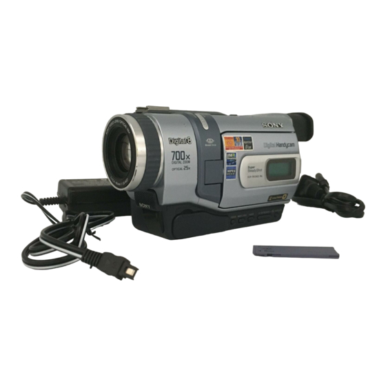
Sony DCR-TRV240E Supplemental Service Manual
Hide thumbs
Also See for DCR-TRV240E:
- Operating instructions manual (288 pages) ,
- Service manual (27 pages)
Advertisement
Table of Contents
DCR-TRV240E/TRV340E
SERVICE MANUAL
Level 2
Ver 1.3 2002. 09
• This supplement-1 is issued for DCR-TRV240E (AEP, UK, East European, North
European, Russian)/TRV340E (AEP, UK, East European, North European, Russian)
model only.
• This supplement-1 has no relation with other models.
Subject
• The LCD assembly Type SO (123k) is added to the conventional Type SO (61k).
In accordance with the addition of Type SO (123k), Schematic diagram, adjustment
and repair parts list of the PD-160 board are changed.
• To check the LCD Type, refer to "LCD Type Check of SECTION 5. 1-5 LCD SYSTEM
ADJUSTMENT".
• There are combinations of the LCD assembly and the PD-160 board, use them in
the combination as shown below.
LCD Panel
PD-160 Board
Fluorescent Cold
Cathode Tube
SUPPLEMENT-1
File this supplement-1 with Service Manual.
LCD Type SO (61k)
ACX308AK-1
8-753-050-65
PD-160 (X6) BOARD, COMPLETE
A-7078-052-A
1-518-796-11
Hong Kong Model
Australian Model
East European Model
North European Model
Russian Model
DCR-TRV240E/TRV340E
Chinese Model
Tourist Model
LCD Type SO (123k)
INDICATOR MODULE LIQUID CRYST
8-753-050-80
PD-160 (X12) BOARD, COMPLETE
A-7078-372-A
1-518-798-22
RMT-814
AEP Model
UK Model
E Model
DCR-TRV340E
Advertisement
Table of Contents

Subscribe to Our Youtube Channel
Summary of Contents for Sony DCR-TRV240E
- Page 1 SUPPLEMENT-1 DCR-TRV340E File this supplement-1 with Service Manual. • This supplement-1 is issued for DCR-TRV240E (AEP, UK, East European, North European, Russian)/TRV340E (AEP, UK, East European, North European, Russian) model only. • This supplement-1 has no relation with other models.
- Page 2 DCR-TRV240E/TRV340E For Schematic Diagram • Refer to page 4-23 for printed wiring board. (Page 4-27) ( ) : Page No. shown in ( ) indicates the page to refer on the original Service Manual. • Refer to page 4-92 for waveforms.
- Page 3 DCR-TRV240E/TRV340E For Schematic Diagram • Refer to page 4-23 for printed wiring board. (Page 4-29) ( ) : Page No. shown in ( ) indicates the page to refer on the original Service Manual. • Refer to page 4-92 for waveforms.
-
Page 4: Section 5. Adjustments
DCR-TRV240E: E, AUS, HK DCR-TRV240E: E, AUS, HK DCR-TRV340E: E, AUS, HK, CH, JE DCR-TRV340E: E, AUS, HK, CH, JE DCR-TRV240E: AEP, UK, EE, NE, RU DCR-TRV340E: AEP, UK, EE, NE, RU 1-2. INITIALIZATION OF 8, A, B, C, D, E, F, 1-2. -
Page 5: Lcd System Adjustment
LCD SYSTEM ADJUSTMETNT (LCD TYPE SO) (PD-160 board) SO) (PD-160 board) * LCD TYPE SO ..DCR-TRV240E: E, AUS, HK * LCD TYPE SO ..DCR-TRV240E: E, AUS, HK DCR-TRV340E: E. AUS, HK, CH, JE DCR-TRV340E: E. AUS, HK, CH, JE... - Page 6 DCR-TRV240E/TRV340E : Changed portion. Page After change Before change 3. RGB AMP Adjustment (PD-160 board) 3. RGB AMP Adjustment (PD-160 board) Mode VTR stop Mode VTR stop Signal No signal Signal No signal Measurement Point Pin 3 of CN5502 (VG)
-
Page 7: Lcd Section
R5523 1-218-990-11 SHORT 0 (AEP,UK,EE,NE,RU) Note : To check the LCD Type refer to “LCD Type Check of SEC- TION5. 1-5 LCD SYSTEM ADJUSTMENT”. (Page 5-31) 2002I1600-1 Sony EMCS Co. 9-929-931-81 ©2002.9 — 10 — Published by DI Customer Center...


Need help?
Do you have a question about the DCR-TRV240E and is the answer not in the manual?
Questions and answers