
Subscribe to Our Youtube Channel
Related Manuals for Fairchild FEB107-001


Summary of Contents for Fairchild FEB107-001
- Page 1 FEB107-001 User’s Guide 240W PFC/PWM Combo Evaluation Board Featured Fairchild Product: FAN4803 www.fairchildsemi.com/FEBsupport ©2004 Fairchild Semiconductor Page 1 of 14 Rev 2.0 3/2/05...
-
Page 2: Table Of Contents
Contents 1. General Board Description ........................3 1.1 The contents of the FEB107-001 Evaluation Kit ..................3 1.2 Power Supply Specification Table ......................3 1.3 FEB107-001 Schematic ........................4 2. Test Procedure............................5 3. Test Results .............................5 3.1 Performance Data..........................5 3.2 Power Ratings ..........................5 4. -
Page 3: General Board Description
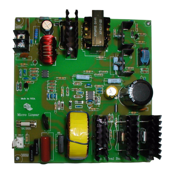
1. General Board Description The FEB107-001 Evaluation Board is a power factor corrected 12V 20A off-line power supply. It is designed to meet IEC1000-3-2 over the universal input voltage range of 85 to 265VAC. The Evaluation Board demon- strates that the FAN4803 can be designed with a low cost single sided PCB at a power level, size, and cost that is compatible with most desk top computer power supply requirements. -
Page 4: Feb107-001 Schematic
9.09k CR16 1000µF R173.3k 1µF 0.1µF 1µF 2.37k FAN4803 (Detail Below) Figure 2. FEB107-001 Schematic PFC OUT PWM OUT SENSE LIMIT TOP VIEW Figure 3. FAN4803 Pin Configuration © 2005 Fairchild Semiconductor Page 4 of 14 Rev 2.0 March 2005... -
Page 5: Test Procedure
3.2 Power Ratings The FEB107-001 Evaluation Board is designed to deliver up to 240 Watts at 85VAC when used with a properly rated and positioned cooling fan. The power rating without a fan is limited to 150 Watts. A 12V fan can be placed as suggested in Figure 1 and operated from the evaluation board 12V output. - Page 6 4.75" sq. x 1.25" thick Flow Figure 4: Fan Position © 2005 Fairchild Semiconductor Page 6 of 14 Rev 2.0 March 2005...
-
Page 7: Feb107-001 Evaluation Kit Parts List
4. FEB107-001 Evaluation Kit Parts List Item Description Ref. Vendor Part Number Resistors Resistor 36 Ohm, 5%, 0.25W, Thru Hole R1, R2, R5, R8 Mouser 30BJ250-36 / any Resistor 0.15 Ohm, 5%, 3W, Wirewound, Huntington Electric ALSR-3J-.15 Thru Hole... - Page 8 FEB107-001 Evaluation Kit Parts List (continued) Item Description Ref. Vendor Part Number Thermistor 10 Ohm, 5A RMS, DigiKey KC006L-ND Thru Hole - Disc ThermoDisc F503EL THERMOMETRICS, INC. CL-50 Capacitors Capacitor 220µF, 20%, 450VDC, Panasonic ECO-S2WB221CA Electrolytic, Radial Capacitor 2200µF, 20%, 16VDC,...
- Page 9 FEB107-001 Evaluation Kit Parts List (continued) Item Description Ref. Vendor Part Number Diode Schottky, 60V, 30A , TO-247, FSID: Fairchild MBR3060PT MBR3060PT Diode Ultra-Fast, 600V, 1A, 75ns, CR3. CR4 Fairchild UF4005 DO-41, FSID: UF4005 Diode Zener, 16V, 0.5W , DO-35, FSID:...
-
Page 10: Vendors For Parts
FEB107-001 Evaluation Kit Parts List (continued) Item Description Ref. Vendor Part Number Heat Sink Tube, Berquist SPT400 Ref. CR1, Q2, Berquist SPT400 11-25 11-25 Heat Sink Tube, Berquist SPT400 13.5-25 Ref. CR2 Berquist SPT400 13.5-25 Heat Sink Twisted Fin, TO-220, AAVID Ref. -
Page 11: Printed Circuit Board
3. CORE & BOBBIN CORE: EE4035 BOBBIN: EE4035 6. Printed Circuit Board The PCB is a single layer board constructed of FR4. 6.1 PCB Silkscreen Figure 3: FEB107-001 PCB top silkscreen © 2005 Fairchild Semiconductor Page 11 of 14 Rev 2.0 March 2005... -
Page 12: Layout Considerations
6.2 Layout considerations The FEB107-001 Evaluation board contains high impedance, low level signals and low impedance, high level circuits. Consequently, it requires extra care in component placement, grounding and PC trace routing. In order to shield low level circuits from the high level signals, the control circuits are placed in surface mount form on the bottom side of the board. -
Page 13: Resources/References
OVP with PFC Soft Start 8. Resources/References 8.1 Application Notes Application Note AN-42043 - ML4803 240W Off-Line Power Supply with PFC Application Note AN-42047 - Power Factor Correction (PFC) Basics © 2005 Fairchild Semiconductor Page 13 of 14 Rev 2.0 March 2005... - Page 14 © 2005 Fairchild Semiconductor Page 14 of 14 Rev 2.0 March 2005...
- Page 15 Mouser Electronics Authorized Distributor Click to View Pricing, Inventory, Delivery & Lifecycle Information: Fairchild Semiconductor FEB107...
Need help?
Do you have a question about the FEB107-001 and is the answer not in the manual?
Questions and answers