Table of Contents
Advertisement
Advertisement
Table of Contents

Related Manuals for Telkom OPTICON MICRO


Summary of Contents for Telkom OPTICON MICRO
- Page 1 OPTICON MICRO Installation & Operation Manual...
-
Page 2: Table Of Contents
OptiCon Micro Installation and Operation Manual Table of Contents Abbreviation list .................... 1 1. INTRODUCTION ..................2 1.1 Manual Usage ....................... 2 1.2 Contents in Package ....................2 1.3 Configuration ......................3 1.4 System Capability ....................4 1.4.1 Description ........................4 1.5 Important Safety Information ................ - Page 3 OptiCon Micro Installation and Operation Manual 2.4.3 LWS-WK Connection ...................... 14 2.4.4 Wireless Handset Connection ..................15 2.4.5 Foot Stand Connection (the LWS-BS and LWS-WK) ............16 2.5 Hardware Installation ..................17 2.5.1 Wall Mounting of the LWS-BS or the LWS-WK ..............17 2.6 Component Description ..................
- Page 4 OptiCon Micro Installation and Operation Manual 2.13 Menu Trees ....................... 30 2.13.1 LWS-BS Menus ......................30 2.13.2 LWS-WK Menus ......................30 2.14 System Capacities ....................31 3. OPERATION INSTRUCTIONS ..............32 3.1 Call Forward ......................32 3.2 Call Pick-up ......................34 3.2.1 Directed Call Pick-Up .....................
- Page 5 OptiCon Micro Installation and Operation Manual 3.15.3 System Speed Dial ....................... 44 3.16 VSF Integrated Auto Attendant/Voice Mail ............45 3.16.1 VSF ..........................45 3.16.2 Auto Attendant Announcement (DISA Service) ............45 3.16.3 Auto Attendant Recording (Leave Voice message) ............47 3.17 Wake-Up Alarm ....................
- Page 6 OptiCon Micro Installation and Operation Manual 3.31 Database management ..................70 3.31.1 Initialize Database ....................... 70 3.31.2 Database backup ......................70 3.31.3 Database Restore ......................71 3.32 Feature Codes ....................71 4. USEFUL INFORMATION ................72 4.1 Trouble shooting ....................72...
-
Page 7: Abbreviation List
OptiCon Micro Installation and Operation Manual Abbreviation list LWS-BS: LG Wireless System - Base Station LWS-WK: LG Wireless System - Wireless Keyset DECT: Digital Enhanced Cordless Telecommunication TDMA: Time Division Multiple Access AC/DC: Alternating Current/Direct Current SLT: Single Line Telephone... -
Page 8: Introduction
1. INTRODUCTION This „Installation & Operation Manual‟ is designed to provide general system features and operating instructions of the OptiCon Micro System. This wireless telephone system is compliant to Digital Enhanced Cordless Telecommunication (DECT) specification, using carrier frequencies from 1.88GHz to 1.9GHz and provides the best in voice quality and design. -
Page 9: Configuration
OptiCon Micro Installation and Operation Manual LWS-WK (Wireless terminal) Power Adapter Quick User Guide AC power cord Figure 1.2-2 LWS-WK Package Contents 1.3 Configuration The following image depicts a sample configuration using the LWS-BS system and the wireless telephone, i.e.: LWS-WK and GDC-400H/450H. -
Page 10: System Capability
OptiCon Micro Installation and Operation Manual 1.4 System Capability 1.4.1 Description Lines: up to 3 Cordless Handsets: up to seven cordless handsets (provided separately) LWS-BS Station 1 Station 2 Station 3 Station 4 Station 5 Station 6 Station 7 Figure 1.4-1 LWS-BS and GDC-400H/450H... -
Page 11: Important Safety Information
Installation and Operation Manual 1.5 Important Safety Information Read this information before installing your OptiCon Micro. Failure to comply with these guidelines could prove either dangerous or illegal. This information helps to avoid personal injury, damage to the phone, or other property damage. -
Page 12: Installation
2. Use a protector to prevent the cables from being stepped on if cables are placed on the floor. Avoid placing wiring under carpets. 3. Avoid using the power supply outlet for the OptiCon Micro with computers, fax machine, and other office equipment to prevent induction noise interruption. -
Page 13: Cell Coverage
OptiCon Micro Installation and Operation Manual Wireless Terminal (GDC-400H, 450H,LWS-WK) DCTU Specifications Item Specification Transmission Max Power 250mW Access Method/Duplex TDMA/TDD Frequency Band 1,880 ~ 1,900MHz Channel Spacing 1.728MHz Modulation GFSK Data rate 1.152Mbps Wireless Terminal Specifications Item Specification Max. -
Page 14: Battery Installation
3. Close the battery cover and slide it upward until it clicks into place. Figure 2.3.1-1 Handset Battery Installation NOTE: Purchase new batteries from your Telkom Service Centre. The battery has limited operating life (warranty period for the battery is 6 months from purchasing date). - Page 15 OptiCon Micro Installation and Operation Manual 2.3.1.1 GDC-400H Battery Charging To charge the handset: Place handset in the plugged-in charger for 12 hours before initial use. Figure 2.3.1.1-1 GDC-400H Handset Battery Charging...
-
Page 16: Gdc-450H Handset Battery Installation
3. Close the battery cover and slide it upward until it clicks into place. Figure 2.3.2-1 GDC-450H Handset Battery Installation NOTE: Purchase new batteries from your Telkom Service Centre. The battery has limited operating life (warranty period for the battery is 6 months from purchasing date). -
Page 17: Lws-Bs, Handset And Peripheral Connections
3. Connect the 3 line cords and the FAX/SLT line cord of the Lightning Protection Kit to the Line and FAX/SLT sockets on the bottom of the LWS-BS. 4. Connect the Telkom exchange line wall sockets to the Line sockets of the Lightning Protection Kit... - Page 18 OptiCon Micro Installation and Operation Manual using the line cords provided. Connect the FAX machine (or SLT phone) line cord to the FAX/SLT socket on the Lightning Protection Kit. 5. Connect the handset curly cord to the handset jack on the bottom of the LWS-BS.
-
Page 19: Fax Connection
OptiCon Micro Installation and Operation Manual 2.4.1 FAX Connection The following figure illustrates how to connect a FAX to the LWS-BS. Please make sure that the Fax line cord is connected to the Lightning protection Kit and the other side of the Lightning Protection Kit to the LWS-BS. -
Page 20: Lws-Wk Connection
OptiCon Micro Installation and Operation Manual 2.4.3 LWS-WK Connection To connect the LWS-WK to be used with the LWS-BS: 1. Plug the DC outlet of the AC/DC Adapter cord into the jack on the LWS-WK. 2. Fasten the AC/DC Adapter cord to the latch hook as shown (inset detail). -
Page 21: Wireless Handset Connection
OptiCon Micro Installation and Operation Manual 2.4.4 Wireless Handset Connection To connect a Wireless Handset to be used with the system: 1. Plug in the AC adapter cord to the Handset Charger and plug AC outlet to the power outlet. -
Page 22: Foot Stand Connection (The Lws-Bs And Lws-Wk)
OptiCon Micro Installation and Operation Manual 2.4.5 Foot Stand Connection (the LWS-BS and LWS-WK) When the Foot Stand of either the LWS-BS or the LWS-WK is attached, the angle of the phone can be adjusted to 35 or 55 degrees. -
Page 23: Hardware Installation
OptiCon Micro Installation and Operation Manual 2.5 Hardware Installation 2.5.1 Wall Mounting of the LWS-BS or the LWS-WK To wall mount the LWS-BS or LWS-WK, perform the following: 1. Remove the foot stand. 2. Make sure the handset retainer tab is positioned at „b‟ as shown below figure. -
Page 24: Component Description
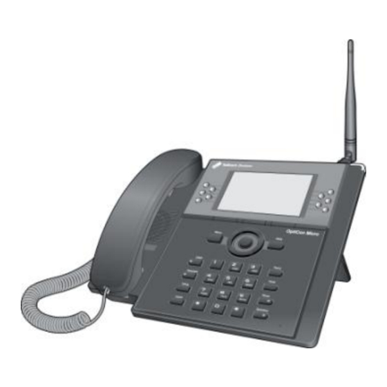
OptiCon Micro Installation and Operation Manual 2.6 Component Description 2.6.1 LWS-BS Description 1. Handset 2. Navigation/OK Key 3. Speaker 4. Menu Button 5. DND Button 6. Headset Button 7. Volume Up Button 8. Volume Down Button 9. Antenna 10. Ring Indication 11. -
Page 25: Lws-Wk Description
OptiCon Micro Installation and Operation Manual 2.6.2 LWS-WK Description 1. Handset 2. Navigation/OK Key 3. Speaker 4. Menu Button 5. DND Button 6. Headset Button 7. Volume Up Button 8. Volume Down Button 9. Ring Indication 10. LCD 11. Line/Station Selection Buttons 12. Soft Buttons 13. -
Page 26: Wireless Dect Handset Description
OptiCon Micro Installation and Operation Manual 2.6.3 Wireless DECT Handset Description Figure 2.6.3-1 GDC-400H Component Description Figure 2.6.3-2 GDC-450H Component Description... -
Page 27: Hardware Initialization
OptiCon Micro Installation and Operation Manual 2.7 Hardware Initialization 2.7.1 LWS-BS and LWS-WK Once the LWS-BS and the LWS-WK have been properly installed in the desired location, perform the following: 1. Plug in the AC/DC adapter to the LWS-BS or the LWS-WK (use only the included AC/DC adapter, SA-B122). -
Page 28: Lcd Display
OptiCon Micro Installation and Operation Manual 2.8.2 LCD Display 2.8.2.1 LWS-BS Figure 2.8.2.1-1 LWS-BS LCD Display Screen 1. Antenna – LCD displays when DCTU of LWS-BS works and it can be linked to DECT. 2. Call Forward – Icon indicates the base station is currently set for call forwarding. -
Page 29: Keypad Description
OptiCon Micro Installation and Operation Manual 2.8.2.3 GDC-400H and GDC-450H Wireless Handset 1. Antenna – Displayed when the handset is in the range of a LWS-BS where it can be linked. The antenna icon disappears when it moves out of range. The closer it moves to the base, the stronger RSSI will be. -
Page 30: Lws-Wk
OptiCon Micro Installation and Operation Manual Mute During a conversation, pressing the [MUTE] button to disable the handset microphone or the speakerphone while continuing to listen to the other. Pressing the [MUTE] button again, will reactivate the microphone. This button is active on all calls. -
Page 31: Gdc-400H/450H Wireless Handset
OptiCon Micro Installation and Operation Manual 2.9.3 GDC-400H/450H Wireless Handset Button Function [TALK] Try to make a call Redial number saved in handset. [END/POWER] Pressing longer than 1 second : Power Off Pressing shorter than 1 second :Leave a call back or a message ... -
Page 32: Led Operation Description
OptiCon Micro Installation and Operation Manual Button Function [CALL BACK] Pressing shorter than 1 second : Leave a call back or a message [UP/DOWN] Talking Mode : Increase/decrease received audio volume, Call by name, CLIP Standby Mode : ... -
Page 33: Configuration
3. If you want to change the country, press the [CHANGE] soft key or the [OK] Navigation key. 4. Set the Nation code. *27 for Telkom. 5. When finished, press the [SAVE] button, and system will ask you to confirm it. -
Page 34: Terminal Registration And Termination
OptiCon Micro Installation and Operation Manual 2.12 Terminal Registration and Termination The LWS-BS controls the functional service and registration of the LWS-WK and GDC-400H/450H. First of all, they should be subscribed to LWS-BS before used. 2.12.1 Subscribing the GDC-400/450H / LWS-WK to LWS-BS Only one Wireless Handset or Keyset can be registered at a time. -
Page 35: Terminating A Subscriptions
OptiCon Micro Installation and Operation Manual Note: : [Menu], [OK] button on GDC-400H : [Menu], [OK] button on GDC-450H RFPI : Radio Fixed Part Identity Seven Wireless Handsets and/or Keysets can be registered to one LWS-BS. -
Page 36: Menu Trees
OptiCon Micro Installation and Operation Manual Procedure for erasing the registration information on the terminal itself: 1. Press the [Menu] button. 2. Select [Phone Register] and press the [OK] button. 3. Select [Reset] on the Menu and press the [OK] button. -
Page 37: System Capacities
OptiCon Micro Installation and Operation Manual 2.14 System Capacities The OptiCon Micro is presently available in one configuration only as shown in the Table 2.14.1. Table 2.14.1 OptiCon Micro System Capacity Chart DESCRIPTION REMARK CAPACITY Stations LWS-BS station Wireless Terminal... -
Page 38: Operation Instructions
OptiCon Micro Installation and Operation Manual 3. OPERATION INSTRUCTIONS 3.1 Call Forward Description Users may have selected incoming calls re-routed to other stations or voice mail. Forward feature is applied to internal calls, auto attendant line calls, & normal line calls with ring assigned only to one station. - Page 39 OptiCon Micro Installation and Operation Manual Conditions 1. A station receiving a forwarded call can transfer the call to the forwarding station. 2. Calls cannot be forwarded to a station in DND; if attempted, an error tone is returned. 3. Call Forward status is maintained in the system‟s non-volatile memory for protection from power outage.
-
Page 40: Call Pick-Up
OptiCon Micro Installation and Operation Manual 3.2 Call Pick-up 3.2.1 Directed Call Pick-Up Description A station may answer calls ringing at another station (Call Pick-Up). All ringing calls are subject to Directed Call Pick-up except Queue Call-backs. Operation To Pick-up a call ringing at another station: LWS-BS station and LWS-WK 1. -
Page 41: Call Transfer
3.3 Call Transfer Description Line calls can be transferred to other stations in the OptiCon Micro system. Calls can be transferred announcing the call (screened) or without an announcement (unscreened). When a Line call is transferred, the Transfer Recall Timer (30sec) is initiated. If the timer expires before the call is answered, the Hold Recall process is initiated. - Page 42 OptiCon Micro Installation and Operation Manual 3. Dial the telephone number to receive the transfer. 4. When answered, announce the call. 5. Press the ([End] key]) to complete the transfer. While on a call, to perform an Unscreened Call Transfer: LWS-BS station and LWS-WK 1.
-
Page 43: Call Waiting/Camp-On
OptiCon Micro Installation and Operation Manual 3.4 Call Waiting/Camp-On Description Call Waiting is used to notify a busy station that a call is waiting. The busy station is notified of the waiting call with a Camp-On tone. After receiving a busy signal, the calling station camps on to the called station. -
Page 44: Three-Party Voice Conference
OptiCon Micro Installation and Operation Manual 3.6 Three-Party Voice Conference Description The system will allow a three party conference (internal and/or external parties can be connected on a conference call. Only the LWS-BS station may initiate a conference call. If the base station goes on- hook the conference will be terminated. -
Page 45: Dnd (Do Not Disturb)
OptiCon Micro Installation and Operation Manual 3.8 DND (Do Not Disturb) Description A station can be placed in DND to block incoming Line calls, Intercom calls and transfers. Operation To activate DND: LWS-WK Press the [DND] button; the [DND] button LED illuminates. -
Page 46: Hold
OptiCon Micro Installation and Operation Manual Operation LWS-BS station To select Headset mode: Press the [Headset] button. The LED of [Headset] button is turned on. To place/answer calls using the headset: Press the [Speaker] with the phone in Headset mode. -
Page 47: Hold Recall
OptiCon Micro Installation and Operation Manual Conditions When a Line is placed on System Hold, the button LED will flash (it will flash at the holding station and will flash at all other stations). A call on System Hold can be retrieved from any station allowed access to the Line in the system database using the Line button or the Held Line call access code. -
Page 48: Cid Blacklist
OptiCon Micro Installation and Operation Manual 3.12 CID Blacklist Description The system can employ the Caller identification number to determine the routing of incoming external calls. The system will compare the received Caller ID to entries in the CID Blacklist, and if a match is found, will route the call to the Voice mail of base station or disconnect the call. -
Page 49: Speed Dial
OptiCon Micro Installation and Operation Manual Operation LWS-BS station To record a VSF message for MOH: Press the [Menu] button. Dial 2 4. Dial „#‟. After the record prompt and beep-tone, record message. Press the [Save] button to stop recording and save the MOH message. -
Page 50: System Speed Dial
OptiCon Micro Installation and Operation Manual To program an Individual Speed Dial number: Press the [Directory] button. Press the [Speed] button. Press the [Add] button. Dial the Speed Dial bin number (00-19). Press the {Line} button or dial the Line access code (ex. 0 or 8801 ~ 8803). -
Page 51: Vsf Integrated Auto Attendant/Voice Mail
3.16.1 VSF Description The Voice Store & Forward (VSF) unit, which is equipped in the OptiCon Micro, provides the system memory to support the integrated Auto Attendant, Voice Mail, and system announcement applications available in the System. The memory is employed to store Auto Attendant announcements, voice mail, greetings, and messages, and various system prompts. - Page 52 OptiCon Micro Installation and Operation Manual If „COMMON” is recorded, and “LINE 1” is also recorded, then “COMMON” is applied to line 2 and line 3, and “LINE 1” is applied to line 1. If the caller dials a station number, the Auto Attendant will complete an unsupervised call transfer to the station.
-
Page 53: Auto Attendant Recording (Leave Voice Message)
OptiCon Micro Installation and Operation Manual 3.16.3 Auto Attendant Recording (Leave Voice message) Description When a Line is set “Auto Attendant” to “ON”(Menu 2 3 1) and “Auto Atd destination” to “System VM”(Menu 2 3 7), if a call comes into the system through the Line, the call is routed to “System voice mail”.(refer to the 3.27 System voice mail), caller can leave a message. - Page 54 OptiCon Micro Installation and Operation Manual Description When a station activates Call Forward to the VSF, calls to the station will forward to the station VSF mailbox. The caller receives the called station‟s User Greeting followed by a beep tone.
- Page 55 OptiCon Micro Installation and Operation Manual Prompts are then received to guide the user in the Voice Mailbox operation. The user must enter a Mail Box number, generally the station number, and a corresponding password in response to the "Request for Password"...
- Page 56 OptiCon Micro Installation and Operation Manual LWS-WK Press [Speaker] button. Press {Change VM password} code (ex.559). If a current password exists, enter the station number and current password. Press [Hold] button. Enter the station number and new password Press [Hold] button in LWS-WK.
- Page 57 OptiCon Micro Installation and Operation Manual GDC-400H/450H Press the ([Talk] key). Press Dial the {Voice mail} code (ex. 620). Dial the Mailbox number (station number) and corresponding password to receive the “Number of Messages” prompt. Dial desired option code. At completion of session, press the ([End] key) to return to idle.
- Page 58 OptiCon Micro Installation and Operation Manual 3.16.4.4 Message Retrieval Options Description The user may dial the digit „9‟ to receive the “VM Long Options” prompt while in the Voice Mailbox, including during or after a voice message or system prompt, except when an option has been selected that requires user dialing.
- Page 59 OptiCon Micro Installation and Operation Manual To enter a new password: Dial „7‟ to receive the “Password Entry” prompt (“Please enter your new password and press pound when finished."). Dial new password. Press „#‟; the “Re-enter Password” prompt will be heard ("Please re-enter your password to confirm and press pound when finished.").
-
Page 60: Wake-Up Alarm
OptiCon Micro Installation and Operation Manual To activate Call Forward: Dial „1‟ and receive the “Destination Entry” prompt (“Please enter the number to forward to"). Dial the Station Number as follows: To forward to another station, dial the station number. -
Page 61: Intercom Call (Icm Call)
OptiCon Micro Installation and Operation Manual Dial 5 4. Select “Single” or “Continuous” Dial 2-digit hour and 2-digit minute for alerting. Press the [Save] button. To erase Wake-Up: LWS-BS station Press the [Menu] button. Dial 5 4. Select “OFF”. Press the [Save] button. -
Page 62: Intercom Call Hold
OptiCon Micro Installation and Operation Manual 3.19 Intercom Call Hold Description While on an active ICM Call, Users can place the ICM Call on hold; the held station will receive the assigned MOH. The call is placed on Exclusive Hold and recalls at the holding station after the station returns to idle. -
Page 63: Night/Weekend Mode
OptiCon Micro Installation and Operation Manual Conditions A busy station receives muted ring or Call Waiting tones (as appropriate) for the station‟s off-hook ring assignment. In Night/weekend mode, Line ring assignment is disabled. In case of the GDC-400H/450H and LWS-WK, a maximum of 6 stations can be assigned for each line. -
Page 64: Mute
OptiCon Micro Installation and Operation Manual Operation LWS-BS station To place a call with Call Log: Press the [Call log] soft button. Select “received” , “dialed” or “missed” Select the desired number and press [Send] soft button. To delete Call Log: Press the [Call log] soft button. -
Page 65: Tel/Fax Line
OptiCon Micro Installation and Operation Manual 3.24 Tel/Fax Line Description If Tel/Fax Line Mode (Menu 1 3 1) is selected, the system will detect a FAX tone within the fax tone detection time. After detecting FAX tone, the system sends the call to the SLT/FAX port to respond to it. -
Page 66: Slt Hot Line
OptiCon Micro Installation and Operation Manual Conditions 1. Calls to SLT/Fax port cannot be picked up. 2. The Camp-on feature is not allowed to a busy SLT/Fax port. 3. Voice messaging is not available for the SLT/Fax port. Programming Modem – [Menu] + 3 4 7 UPPLEMENTARY 3.25.2 SLT Hot Line... -
Page 67: Phone Book (Gdc-400H/450H & Lws-Wk)
OptiCon Micro Installation and Operation Manual Conditions 1. The Forward feature is not available for SLT/Fax port. 2. Calls to SLT/Fax port cannot be picked up. 3. The Camp-on feature is not allowed to a busy SLT/Fax port. Voice messaging is not available for the SLT/Fax port. -
Page 68: Edit Co Code
OptiCon Micro Installation and Operation Manual GDC-400H/450H 1. Press the Option ( ) left soft button; this displays the Options menu. 2. Use the [Navigation] ( ) button to highlight Phonebook and press the OK ( ) left soft button. -
Page 69: Adding Records To The Phonebook
OptiCon Micro Installation and Operation Manual Operation To dial a number from the Phonebook: LWS-WK 1. Access the Phonebook menu, see section 3.26 above. 2. Use the [Navigation] button to highlight the Find selection and press the [OK] soft button; the “Enter Name”... -
Page 70: Modifying Records In The Phonebook
OptiCon Micro Installation and Operation Manual GDC-400H/450H 1. Access the Phonebook menu as described in section 3.26 above. 2. Use the [Navigation] button ( ) to highlight Add Entry selection and press the [OK] ( left soft button. 3. Enter the name using the dial pad, up to 14 characters, (see section 3.26.6 Dial pad Character Charts), and press the [OK] ( ) left soft button. -
Page 71: Deleting Records From Phonebook
OptiCon Micro Installation and Operation Manual 3.26.5 Deleting records from Phonebook Operation To delete a record from the Phonebook: LWS-WK 1. Access the Phonebook menu as described in section 3.26 above. 2. Use the [Navigation] button to highlight the Delete selection and press the [OK] soft button. -
Page 72: Dial Pad Character Charts
OptiCon Micro Installation and Operation Manual 3.26.6 Dial pad Character Charts Description The GDC-400H/450H/LWS-WK Phonebook permits names to be associated with a Phonebook record. The following charts provide the correlation between the dial pad digits and characters. Charts are available for English, Italian, Spanish, and Russian. To insert a character, each dial pad button is pressed one or more times to select the desired character. - Page 73 OptiCon Micro Installation and Operation Manual Station number, Station Speed (speed number 00~19, only LWS-BS), System Speed (speed number 200~999), Line access code, Pickup code. Operation To assign a station to a button, 1. Press the [Speaker] button. 2. Press the [Trans] button.
-
Page 74: System Voice Mail
1. The SLT/Fax port cannot be assigned for “System voice mail”. 3.29 SMDR Information Description SMDR information for all incoming and outgoing calls is available on default on the OptiCon Micro LAN port. Only change IP information of OptiCon Micro for output to call logging/management systems. -
Page 75: Software Upgrade
3.30 Software Upgrade Description The OPTICON MICRO system and LWS-BS phone software can be upgraded employing the USB port located on the bottom of the LWS-BS. The system and/or LWS-BS software file(s) must be separately loaded on the USB memory device before insertion into the LWS-BS USB port. Two types of software files,... -
Page 76: Database Management
3.31 Database management Description From the DB Management menu, the database of the OPTICON MICRO system can be initialized, stored as a backup copy on a USB device, or loaded to the system from a USB device. Note that the Voice mail messages cannot be backed up or restored. -
Page 77: Database Restore
1. The backup function does not copy (backup) the Voice messages in the OPTICON MICRO system. 3.31.3 Database Restore Description A USB device that has a copy of the OPTICON MICRO database can be used to recover or copy the database to a OPTICON MICRO system. Operation To restore DB: LWS-BS station Insert a USB memory device with a database to the USB port on the bottom of the LWS-BS. -
Page 78: Useful Information
If you experience any problems with the normal use of your phone, you should first power-off and disconnect the base station. Then connect it and connect the power again. If the phone continues to have problems, please check the following Table before contacting the Telkom Service centre. PROBLEM... - Page 79 OptiCon Micro Installation and Operation Manual turn-on the system again. Note: SYSTEM ADMIN PASSWORD: Should you set an ADMIN Password via Menu item 4, 1 on the LWS-BS menu, it is advised that you record this password somewhere safe because should you forget this password a qualified technician is required to reset the password.
Need help?
Do you have a question about the OPTICON MICRO and is the answer not in the manual?
Questions and answers
How to cancell pin code
To cancel the PIN code for Telkom MICRO, follow these steps:
1. Press the [Menu] button.
2. Select [Phone Register] and press [OK].
3. Select [Reset] and press [OK].
4. Enter the HS PIN Code (default is 0000) and press [OK].
5. Select [Handset] and press [OK].
This procedure erases the registration information on the terminal, effectively canceling the PIN code.
This answer is automatically generated