Table of Contents

Related Manuals for EuroLite LED SLS-90 Strobe SMD 5630


Summary of Contents for EuroLite LED SLS-90 Strobe SMD 5630
- Page 1 BEDIENUNGSANLEITUNG USER MANUAL LED SLS-90 Strobe SMD 5630 Für weiteren Gebrauch aufbewahren! © Copyright Keep this manual for future needs! Nachdruck verboten! Reproduction prohibited!
-
Page 2: Table Of Contents
Connection with the mains ........................... 25 Connection between devices ........................25 OPERATION ..............................26 Control Board ............................... 26 EUROLITE IR-7 remote control (optionally available accessories) ............. 27 DMX-controlled operation ..........................28 Addressing ..............................28 DMX Protocol ............................... 29 CLEANING AND MAINTENANCE ......................... 33 Replacing the fuse ............................ -
Page 3: Einführung
- sich die letzte Version der Anleitung im Internet herunter laden EINFÜHRUNG Wir freuen uns, dass Sie sich für ein EUROLITE LED SLS-90 Strobe SMD 5630 entschieden haben. Wenn Sie nachfolgende Hinweise beachten, sind wir sicher, dass Sie lange Zeit Freude an Ihrem Kauf haben werden. - Page 4 Bitte überprüfen Sie vor der ersten Inbetriebnahme, ob kein offensichtlicher Transportschaden vorliegt. Sollten Sie Schäden an der Netzleitung oder am Gehäuse entdecken, nehmen Sie das Gerät nicht in Betrieb und setzen sich bitte mit Ihrem Fachhändler in Verbindung. Der Aufbau entspricht der Schutzklasse I. Der Netzstecker darf nur an eine Schutzkontakt-Steckdose angeschlossen werden, deren Spannung und Frequenz mit dem Typenschild des Gerätes genau übereinstimmt.
-
Page 5: Bestimmungsgemäße Verwendung
BESTIMMUNGSGEMÄßE VERWENDUNG Bei diesem Gerät handelt es sich um einen Effektstrahler, mit dem sich dekorative Lichteffekte erzeugen lassen. Dieses Produkt ist für den Anschluss an 100-240 V, 50-60 Hz Wechselspannung zugelassen und wurde ausschließlich zur Verwendung in Innenräumen konzipiert. Dieses Gerät ist für professionelle Anwendungen, z. B. auf Bühnen, in Diskotheken, Theatern etc. vorgesehen. -
Page 6: Gerätebeschreibung
GERÄTEBESCHREIBUNG Features Per IR-Fernbedienung steuerbares Slimline LED-Strobe mit kaltweißen LEDs • Ausgestattet mit 90 SMD 5630 LEDs • 2, 5, 8 oder 12 DMX-Kanäle wählbar • Weiter Abstrahlwinkel • Flache Gehäuseform für minimalen Platzbedarf bei der Montage • Kompaktes und formschönes Gehäuse •... -
Page 7: Installation
INSTALLATION Das Gerät kann sowohl hängend als auch stehend installiert werden. Überkopfmontage LEBENSGEFAHR! Bei der Installation sind insbesondere die Bestimmungen der BGV C1 und EN 60598-2-17 zu beachten! Die Installation darf nur vom autorisierten Fachhandel ausgeführt werden! Die Aufhängevorrichtungen des Gerätes muss so gebaut und bemessen sein, dass sie 1 Stunde lang ohne dauernde schädliche Deformierung das 10-fache der Nutzlast aushalten kann. -
Page 8: Anschluss An Den Dmx-512 Controller / Verbindung Gerät - Gerät
Befestigen Sie das Gerät über einen geeigneten Haken an Ihrem Traversensystem. Sichern Sie das Gerät bei Überkopfmontage immer mit einem geeigneten Sicherungsseil. Es dürfen nur Sicherungsseile und Schnellverbindungsglieder gemäß DIN 56927, Schäkel gemäß DIN EN 1677-1 und BGV C1 Kettbiner eingesetzt werden. Die Fangseile, Schnellverbindungsglieder, Schäkel und Kettbiner müssen auf Grundlage der aktuellsten Arbeitsschutzbestimmungen (z. -
Page 9: Master/Slave-Betrieb
Aufbau einer seriellen DMX-Kette: Schließen Sie den DMX-Ausgang des ersten Gerätes der Kette an den DMX-Eingang des nächsten Gerätes an. Verbinden Sie immer einen Ausgang mit dem Eingang des nächsten Gerätes bis alle Geräte ange- schlossen sind. Achtung: Am letzten Gerät muss das DMX-Kabel durch einen Abschlusswiderstand abgeschlossen werden. Dazu wird ein XLR-Stecker in den DMX-Ausgang am letzten Gerät gesteckt, bei dem zwischen Signal (–) ... -
Page 10: Bedienung
ENTER, UP, DOWN auswählen. Das Gerät hat drei Betriebsarten. Es kann entweder im Standalone-Modus über das Control Board, über die optional erhältliche EUROLITE IR-7 Fernbedienung oder im DMX-gesteuerten-Modus über einen handels- üblichen DMX-Controller betrieben werden. Bitte beachten Sie weitere Hinweise unter Control Board. -
Page 11: Fernbedienung Eurolite Ir-7 (Optional Erhältliches Zubehör)
Fernbedienung EUROLITE IR-7 (optional erhältliches Zubehör) Die Fernbedienung wird mit eingesetzter Batterie geliefert. Damit die Batterie während der Lagerung nicht entladen werden kann, befindet sich eine Isolierfolie zwischen der Batterien und den Batteriekontakten. Ziehen Sie vor dem ersten Betrieb die Folie auf der Rückseite der Fernbedienung aus dem Batteriehalter heraus. -
Page 12: Dmx-Gesteuerter Betrieb
12-CH anzeigt. Drücken Sie die ENTER-Taste und das Display zeigt d001 an. Sie können nun die gewünschte Adresse über die UP- oder DOWN-Taste auswählen. Bitte drücken Sie noch einmal die ENTER- Taste zur Bestätigung. Nachdem Sie die Startadresse definiert haben, können Sie den LED SLS-90 Strobe SMD 5630 über Ihren Controller ansteuern. Bitte beachten Sie: Über das Display des Gerätes wird der Status der DMX-Verbindung angezeigt:... -
Page 13: Dmx-Protokoll
DMX-Protokoll 2-Kanal-Modus Steuerkanal 1 - Dimmer Decimal Hexad. Percentage Eigenschaft 0 255 00 FF 0% 100% Allmähliche Einstellung der Dimmerintensität von 0 bis 100 % Steuerkanal 2 - Strobe Decimal Hexad. Percentage Eigenschaft 00 05 0% 2% Keine Funktion 6 249 06 F9 2% 98% Strobe-Effekt mit zunehmender Geschwindigkeit... - Page 14 Steuerkanal 5 - Pixelmakros Decimal Hexad. Percentage Eigenschaft 00 05 0% 2% Keine Funktion 6 42 06 2A 2% 16% Makro 1 mit zunehmender Geschwindigkeit 43 85 2B 55 17% 33% Makro 2 mit zunehmender Geschwindigkeit 86 128 56 80 34% 50% Makro 3 mit zunehmender Geschwindigkeit 129 171...
- Page 15 Steuerkanal 7 - Dimmer LED-Kreis 4 Decimal Hexad. Percentage Eigenschaft 0 255 00 FF 0% 100% Allmähliche Einstellung der Dimmerintensität von 0 bis 100 % Steuerkanal 8 - LED-Kreis 4 Decimal Hexad. Percentage Eigenschaft 00 05 0% 2% Keine Funktion 6 249 06 F9 2% 98%...
- Page 16 Steuerkanal 7 - Dimmer LED-Kreis 4 Decimal Hexad. Percentage Eigenschaft 0 255 00 FF 0% 100% Allmähliche Einstellung der Dimmerintensität von 0 bis 100 % Steuerkanal 8 - LED-Kreis 4 Decimal Hexad. Percentage Eigenschaft 00 05 0% 2% Keine Funktion 6 249 06 F9 2% 98%...
-
Page 17: Reinigung Und Wartung
REINIGUNG UND WARTUNG Der Unternehmer hat dafür zu sorgen, dass sicherheitstechnische und maschinentechnische Einrichtungen mindestens alle vier Jahre durch einen Sachverständigen im Umfang der Abnahmeprüfung geprüft werden. Der Unternehmer hat dafür zu sorgen, dass sicherheitstechnische und maschinentechnische Einrichtungen mindestens einmal jährlich durch einen Sachkundigen geprüft werden. Dabei muss unter anderem auf folgende Punkte besonders geachtet werden: 1) Alle Schrauben, mit denen das Gerät oder Geräteteile montiert sind, müssen fest sitzen und dürfen nicht korrodiert sein. -
Page 18: Technische Daten
TECHNISCHE DATEN Spannungsversorgung: 100-240 V AC, 50/60 Hz ~ Gesamtanschlusswert: 24 W DMX-Steuerkanäle: 2/5/8/12 DMX512-Anschluss: 3-pol. XLR Musiksteuerung: über eingebautes Mikrofon Blitzrate: 30 Hz Anzahl der LEDs: LED-Typ: SMD 5630, 6500 K Abstrahlwinkel: 110° Maße (LxBxH): 107 x 170 x 194 mm Gewicht: 1,5 kg Maximale Umgebungstemperatur T... -
Page 19: Introduction
- download the latest version of the user manual from the Internet INTRODUCTION Thank you for having chosen a EUROLITE LED SLS-90 Strobe SMD 5630. If you follow the instructions given in this manual, we are sure that you will enjoy this device for a long period of time. - Page 20 Please make sure that there are no obvious transport damages. Should you notice any damages on the A/C connection cable or on the casing, do not take the device into operation and immediately consult your local dealer. This device falls under protection-class I. The power plug must only be plugged into a protection class I outlet.
-
Page 21: Operating Determinations
OPERATING DETERMINATIONS This device is a lighting effect for creating decorative effects. This product is allowed to be operated with an alternating voltage of 100-240 V, 50-60 Hz and was designed for indoor use only. This device is designed for professional use, e.g. on stages, in discotheques, theatres etc. Lighting effects are not designed for permanent operation. -
Page 22: Description Of The Device
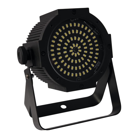
DESCRIPTION OF THE DEVICE Features Slimline LED Strobe with cold white LEDs controllable via IR remote • Equipped with 90 SMD 5630 LEDs • 2, 5, 8 or 12 channels selectable • Wide beam angle • Flat housing form requires minimal space when rigging •... -
Page 23: Installation
INSTALLATION The device can be installed on the ground or on the wall or ceiling. Overhead rigging DANGER TO LIFE! Please consider the EN 60598-2-17and the respective national standards during the installation! The installation must only be carried out by an authorized dealer! The installation of the device has to be built and constructed in a way that it can hold 10 times the weight for 1 hour without any harming deformation. -
Page 24: Dmx-512 Connection / Connection Between Fixtures
dimensioned and used correctly in accordance with the latest industrial safety regulations (e. g. BGV C1, BGI 810-3). Please note: for overhead rigging in public or industrial areas, a series of safety instructions have to be followed that this manual can only give in part. The operator must therefore inform himself on the current safety instructions and consider them. -
Page 25: Master/Slave Operation
Master/Slave operation The master/slave operation enables that several devices can be synchronized and controlled by one master device. On the rear panel of the device you can find an XLR jack and an XLR plug, which can be used for connecting several devices. -
Page 26: Operation
OPERATION After you connected the LED SLS-90 Strobe SMD 5630 to the mains, it starts running. The LED display lights up and you can choose the desired mode via the buttons MODE, ENTER, UP and DOWN. The device has three operating modes. It can be operated in Stand Alone Mode via the Control Board, via optionally available EUROLITE IR-7 remote control or in DMX-controlled mode via every standard DMX controller. -
Page 27: Eurolite Ir-7 Remote Control (Optionally Available Accessories)
EUROLITE IR-7 remote control (optionally available accessories) The remote control is supplied with a battery inserted. An insulating foil between the battery and the battery contacts prevents the battery from being discharged during storage. Prior to the first operation remove the foil from the battery support on the rear side of the remote control. -
Page 28: Dmx-Controlled Operation
CH, 8-CH or 12-CH. Press the ENTER button and the display shows: d001. Set the desired address via the UP or DOWN buttons. Please press the ENTER button again to confirm. Now you can start operating the LED SLS-90 Strobe SMD 5630 via your lighting controller. Note: The modes of DMX512 data are shown via the display of the device: After switching on, the device will automatically detect whether DMX 512 data is received or not. -
Page 29: Dmx Protocol
DMX Protocol 2 channel mode Control-channel 1 - Dimmer Decimal Hexad. Percentage Feature 0 255 00 FF 0% 100% Gradual adjustment of the dimmer intensity from 0 to 100 % Control-channel 2 - Strobe Decimal Hexad. Percentage Feature 00 05 0% 2% No function 6 249... - Page 30 Control-channel 5 - Pixel macros Decimal Hexad. Percentage Feature 00 05 0% 2% No function 6 42 06 2A 2% 16% Macro 1 with increasing speed 43 85 2B 55 17% 33% Macro 2 with increasing speed 86 128 56 80 34% 50% Macro 3 with increasing speed 129 171...
- Page 31 Control-channel 7 - Dimmer LED circle 4 Decimal Hexad. Percentage Feature 0 255 00 FF 0% 100% Gradual adjustment of the dimmer intensity from 0 to 100 % Control-channel 8 - LED circle 4 Decimal Hexad. Percentage Feature 00 05 0% 2% No function 6 249...
- Page 32 Control-channel 7 - Dimmer LED circle 4 Decimal Hexad. Percentage Feature 0 255 00 FF 0% 100% Gradual adjustment of the dimmer intensity from 0 to 100 % Control-channel 8 - LED circle 4 Decimal Hexad. Percentage Feature 00 05 0% 2% No function 6 249...
-
Page 33: Cleaning And Maintenance
CLEANING AND MAINTENANCE The operator has to make sure that safety-relating and machine-technical installations are inspected by an expert after every four years in the course of an acceptance test. The operator has to make sure that safety-relating and machine-technical installations are inspected by a skilled person once a year. -
Page 34: Technical Specifications
TECHNICAL SPECIFICATIONS Power supply: 100-240 V AC, 50/60 Hz ~ Power consumption: 24 W DMX control channels: 2/5/8/12 DMX512 connection: 3-pin XLR Sound-control: via built-in microphone Flash-rate: 30 Hz Number of LEDs: LED type: SMD 5630, 6500 K Beam angle: 110°...
Need help?
Do you have a question about the LED SLS-90 Strobe SMD 5630 and is the answer not in the manual?
Questions and answers