Table of Contents
Advertisement
SERVICE MANUAL
Ver 1.2 2004. 04
Sony Corporation
9-877-111-03
Personal Audio Company
2004D02-1
Published by Sony Engineering Corporation
© 2004.04
SPECIFICATIONS
Recording system
2-track 1 channel monaural
Tape speed
4.8 cm/s or 2.4 cm/s
Frequency range
350 - 6 300 Hz using nomal (TYPE I) cassette (with REC
TIME/PLAY MODE switch at "NORMAL")
Speaker
7
Approx. 3.6 cm (1
/
in.) dia.
16
Power output
450 mW + 450 mW (at 10 % harmonic distortion)
Input
Microphone input jack (minijack)
sensitivity 0.2 mV for 3kΩ or lower impedance microphone
Output
Earphone jack (minijack) for 8 -300Ω earphone
Variable range of the tape speed
From approx. +30% to –15% (with REC TIME/PLAY
MODE switch at "NORMAL")
Power requirements
• 3 V DC, batteries AA (R6) x 2
• External DC 3 V power sources
Dimensions (w/h/d) (incl. projecting parts and controls)
Approx. 87.6 x 113.0 x 37.1 mm
1
1
1
(3
/
x 4
/
x 1
/
in.)
2
2
2
Mass (main unit only)
Approx. 215 g (7.6 oz.)
Design and specifications are subject to change without notice.
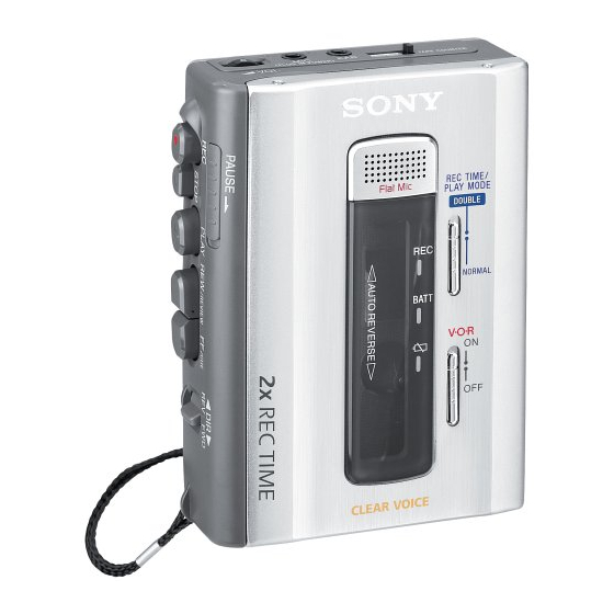
TCM-500DV
Model Name Using Similar Mechanism
Tape Transport Mechanism Type
CASSETTE-CORDER
US Model
Canadian Model
AEP Model
E Model
Tourist Model
New
MT-500-175
Advertisement
Table of Contents

Related Manuals for Sony TCM-500DV


Summary of Contents for Sony TCM-500DV
- Page 1 Approx. 87.6 x 113.0 x 37.1 mm in.) Mass (main unit only) Approx. 215 g (7.6 oz.) Design and specifications are subject to change without notice. CASSETTE-CORDER Sony Corporation 9-877-111-03 Personal Audio Company 2004D02-1 Published by Sony Engineering Corporation © 2004.04...
-
Page 2: Table Of Contents
TCM-500DV TABLE OF CONTENTS GENERAL EXPLODED VIEWS ..........15 ..............2 7-1. Cabinet Section ............15 SERVICING NOTES 7-2. Cassette Holder Section ........16 ..........2 7-3. Mechanism Deck Section-1 (MT-500-175) ..17 DISASSEMBLY ............3 7-4. Mechanism Deck Section-2 (MT-500-175) ..18 3-1. -
Page 3: Disassembly
TCM-500DV SECTION 3 DISASSEMBLY • This set can be disassembled in the order shown below. Mechanism Deck Cabinet (Front) assy (500) MAIN board Lid assy (500), Casette LED board Cabinet Rear assy (500) SP board Head, Magnetic (Rec/Pb/Erase) (HRPE901), Belt (AR), Capstan/Reel Motor (M601) Note: Follow the disassembly procedure in the numerical order given. -
Page 4: Main Board
TCM-500DV 3-2. MAIN BOARD Cabinet (front) assy (500) Orange 2 Flexible board (CN101) Black White 5 MAIN board 1 Remove four solders of capstan/reel motor 3 Screws (M1.4) 3-3. MECHANISM DECK 5 Screws (M1.4 x 2.5) Cabinet (front) assy (500) -
Page 5: Head, Magnetic (Rec/Pb/Erase) (Hrpe901)
TCM-500DV 3-4.HEAD, MAGNETIC (REC/PB/ERASE) (HRPE901), BELT (AR), CAPSTAN/REEL MOTOR (M601) How to attach a belt 3 Belt (AR) 4 Screw (M1.4) 5 Capstan/reel motor (M601) 2 Head, magnetic (rec/pb/erase) (HRPE901) 1 Screw (M1.4) 3-5.LED BOARD Lid assy (500) cassette 8 Mic 901... -
Page 6: Sp Board
TCM-500DV 3-6. SP BOARD 4 Screw 9 SP board 7 Flexible board (CN202) 8 Remove four solders of speaker leads 5 Claws 1 Remove a claw of knob (speed) (600) by a screwdriver Cabinet rear assy (500) 2 Claw 3 Knob (speed) (600) -
Page 7: Mechanical Adjustments
TCM-500DV Ver 1.2 SECTION 4 SECTION 5 MECHANICAL ADJUSTMENTS ELECTRICAL ADJUSTMENTS 1. Clean the following parts with a denatured-alcohol-moistened Torque Measurement Setting: Tape Speed Adjustment swab: • Supplied voltage: 3 V (DC) Mode: playback record/playback/erase head pinch roller Mode Torque Meter Meter Reading •... -
Page 8: Diagrams
TCM-500DV SECTION 6 DIAGRAMS 6-1. BLOCK DIAGRAMS MIC/EARPHONE AMP IC101 B+3V S101 (1/6) S101(3/6) S101(6/6) S101 (2/6) POWER AMP MIC901 IC103 MUTE FLAT MIC IC301 Q701 +OUT(A) IN(A) SP902 SPEAKER S101 (4/6) P.B+ -OUT(A) (R-CH) REC B+ MUTE DRIVE +OUT(B) -
Page 9: Printed Wiring Board -Main Board (Side A)
TCM-500DV 6-2. PRINTED WIRING BOARD –MAIN BOARD (SIDE A)– (SIDE A) MAIN BOARD S102 (POWER) C138 1-687-887- (11) Note: • X : parts extracted from the component side. • : Through hole. • : Pattern from the side which enables seeing. -
Page 10: Printed Wiring Board -Main Board (Side B)
TCM-500DV 6-3. PRINTED WIRING BOARD –MAIN BOARD (SIDE B)– TO HRPE901 (REC/PB/ERASE HEAD) (SIDE B) MAIN BOARD RV101 R705 R704 C704 R708 R713 R616 C604 R603 C610 R712 R612 R610 C607 R609 R618 R617 R606 C601 C609 R613 R406 R614... -
Page 11: Schematic Diagram -Main Board (1/2)
TCM-500DV 6-4. SCHEMATIC DIAGRAM –MAIN BOARD (1/2)– • Refer to page 14 for Notes. -
Page 12: Schematic Diagram -Main Board (2/2)
TCM-500DV 6-5. SCHEMATIC DIAGRAM –MAIN BOARD (2/2)– • Refer to page 14 for Notes. (Page 11) -
Page 13: Printed Wiring Board -Led, Sp Board
TCM-500DV 6-6. PRINTED WIRING BOARD –LED, SP BOARD – LED BOARD MIC901 Flat Mic SP BOARD D401 S401 REC TIME/PLAY MODE RV201 SPEED CONTROL DOUBLE D402 NORMAL BATT CN201 SPEAKER(L) SP901 CN402 D403 MAIN SPEAKER(R) BOARD SP902 (Page 10) MAIN BOARD •... -
Page 14: Ic Block Diagrams
TCM-500DV Note on schematic diagrams • Voltages are taken with a VOM (Input impedance 10 MΩ). • All capacitors are in µF unless otherwise noted. pF: µµF Voltage variations may be noted due to normal produc- 50 WV or less are not indicated except for electrolytics tion tolerances. -
Page 15: Exploded Views
TCM-500DV SECTION 7 EXPLODED VIEWS NOTE: • -XX, -X mean standardized parts, so they may have • The mechanical parts with no reference number in some difference from the original one. the exploded views are not supplied. • Items marked “*” are not stocked since they are •... -
Page 16: Cassette Holder Section
TCM-500DV 7-2. CASSETTE HOLDER SECTION MIC901 Ref. No. Part No. Description Remark Ref. No. Part No. Description Remark 3-375-114-71 SCREW 3-893-942-41 SCREW (1.7X3), TAPPING (B) 3-248-449-01 CUSHION (500), MICROPHONE X-3383-511-1 LID ASSY (500) (U), CASSETTE 3-250-387-01 SPRING (500), GROUND 1-687-886-11 FLEXIBLE BOARD... -
Page 17: Mechanism Deck Section-1 (Mt-500-175)
TCM-500DV 7-3. SMECHANISM DECK SECTION-1 (MT-500-175) A (Included in No.151) HRPE901 M601 Ref. No. Part No. Description Remark Ref. No. Part No. Description Remark 3-704-197-01 SCREW (M1.4), SPECIAL HEAD 3-019-776-03 GEAR (REEL-S) 3-225-429-01 BELT (AR) 3-225-390-03 PULLEY (REVERSE) 3-225-399-04 LEVER (N SHUT OFF) X-3380-830-2 FLY ASSY (AR5.0), CAPSTAN... -
Page 18: Mechanism Deck Section-2 (Mt-500-175)
TCM-500DV 7-4. MECHANISM DECK SECTION-2 (MT-500-175) (Including Ref. No. Part No. Description Remark Ref. No. Part No. Description Remark X-3382-924-1 CHASSIS ASSY (ARS) 3-225-393-03 LEVER (SHUT/OFF) 3-225-385-03 GEAR (B) 3-225-448-02 SPRING (SHUT OFF), TORSION 3-229-063-01 SPRING (UD) (R), COMPRESSION 3-321-813-71 WASHER, COTTER POLYETHYLENE... -
Page 19: Electrical Parts List
TCM-500DV SECTION 8 Ver 1.1 2003.04 MAIN ELECTRICAL PARTS LIST Note: • SEMICONDUCTORS • Due to standardization, replacements in the parts list When indicating parts by reference In each case, u: µ , for example: may be different from the parts specified in the number, please include the board uA...: µ... - Page 20 TCM-500DV MAIN Ref. No. Part No. Description Remark Ref. No. Part No. Description Remark C704 1-115-156-11 CERAMIC CHIP R111 1-216-813-11 METAL CHIP 1/10W R112 1-216-833-11 METAL CHIP 1/10W < CONNECTOR > R114 1-216-813-11 METAL CHIP 1/10W R116 1-216-833-11 METAL CHIP...
- Page 21 TCM-500DV Ver 1.1 2003.04 MAIN Ref. No. Part No. Description Remark Ref. No. Part No. Description Remark R505 1-216-837-11 METAL CHIP 1/10W < VARIABLE RESISTOR > R506 1-216-829-11 METAL CHIP 4.7K 1/10W R601 1-216-809-11 METAL CHIP 1/10W RV201 1-227-445-11 RES, VAR,CARBON30K (SPEED CONTROL)
- Page 22 TCM-500DV REVISION HISTORY Clicking the version allows you to jump to the revised page. Also, clicking the version at the upper right on the revised page allows you to jump to the next revised page. Ver. Date Description of Revision 2003.02...
Need help?
Do you have a question about the TCM-500DV and is the answer not in the manual?
Questions and answers