
Related Manuals for Electro-Voice EVID-S44


Summary of Contents for Electro-Voice EVID-S44
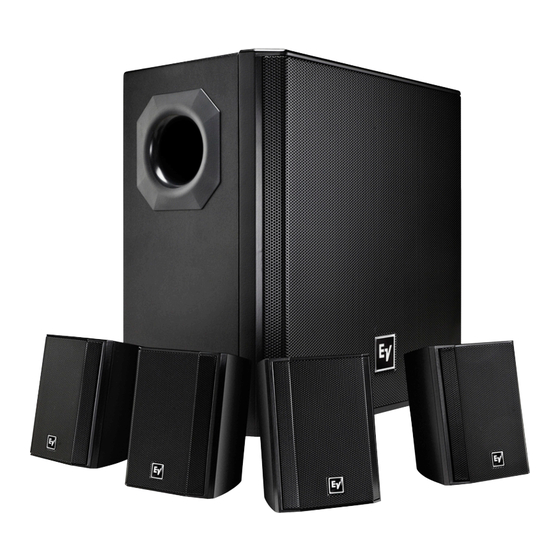
- Page 1 EVID Compact Sound Speaker System EVID-S44, EVID-S44W, EVID-2.1, EVID-2.1W, EVID-40S, and EVID-40SW en | Installation Manual...
-
Page 3: Table Of Contents
Surface mount satellite speaker installation Wall bracket range of motion Surface mount subwoofer installation Removing subwoofer from the wall Wiring Wattage tap 70v/100v/4 ohm Mono 8 ohm Stereo Troubleshooting Technical data Frequency response Electro-Voice Installation Manual 2015.02 | 03 | F.01U.310.295... -
Page 4: Safety
Suspending any object is potentially dangerous and should only be attempted by individuals who have a thorough knowledge of the techniques and regulations of suspending objects overhead. Electro-Voice strongly recommends all loudspeakers be suspended taking into account all current national, federal, state, and local laws and regulations. It is the responsibility of the installer to ensure all loudspeakers are safely installed in accordance with all such requirements. -
Page 5: Welcome
Mounting system for surface mount satellites provides secure mounting but allows for wide-range of motion to adapt to any placement. ▪ Easily detachable wall bracket for wall mounting of subwoofer is included. ▪ Attractive subwoofer design with full face grille. Electro-Voice Installation Manual 2015.02 | 03 | F.01U.310.295... -
Page 6: System Overview
EVID 2.1 surface mount satellite speakers Wall brackets Speaker brackets EVID S44 Engineering Data Sheet M6 hex drive pan-head screws M5 pan-head screws Screw sockets Hex wrench Table 3.1: Surface Mount Satellite Speaker (1 box) 2015.02 | 03 | F.01U.310.295 Installation Manual Electro-Voice... - Page 7 The major components included in the box for the EVID 40S surface mount subwoofer: Item Description Surface Mount Subwoofer Wall bracket, assembled in box EVID Compact Sound Speaker System manual M6 hex drive pan-head screw Rubber feet Hex wrench Table 3.2: Surface Mount Subwoofer Electro-Voice Installation Manual 2015.02 | 03 | F.01U.310.295...
-
Page 8: Product Information
EVID Compact Sound Speaker System Product information Figure 3.1: EVID 2.1 Product Information Figure 3.2: EVID 40C Product Information 2015.02 | 03 | F.01U.310.295 Installation Manual Electro-Voice... -
Page 9: Dimensions
Dimensions Figure 3.3: Dimensions EVID 2.1 and mounting bracket Figure 3.4: Dimensions EVID 40S and mounting bracket Notice! The mounting bracket dimension drawings are not to scale. Drawing sizes increased for readability. Electro-Voice Installation Manual 2015.02 | 03 | F.01U.310.295... -
Page 10: Installation
Place the speaker bracket onto the wall bracket. Using the hex wrench (supplied), tighten the M6 hex drive pan-head screw to secure the speaker bracket to the wall bracket. For more information, see Safety, page 4. 2015.02 | 03 | F.01U.310.295 Installation Manual Electro-Voice... -
Page 11: Wall Bracket Range Of Motion
Only mount the wall bracket in the vertical V-shape position. Do not mount the V-bracket or wall bracket side ways or upside down. Figure 4.2: Wall bracket correct and incorrect mounting positions Electro-Voice Installation Manual 2015.02 | 03 | F.01U.310.295... - Page 12 Using the hex wrench (supplied), tighten the three (3) M6 hex drive pan head screws to attach the V-bracket. Slide the V-bracket into the wall bracket. The locking detents engage. For more information, see Safety, page 4. 2015.02 | 03 | F.01U.310.295 Installation Manual Electro-Voice...
-
Page 13: Removing Subwoofer From The Wall
Removing subwoofer from the wall To remove the subwoofer from the wall, do the following: Pull the subwoofer slightly out from the wall. Lift the subwoofer up. The locking detents disengage. Electro-Voice Installation Manual 2015.02 | 03 | F.01U.310.295... -
Page 14: Wiring
100V, as well as a 4 ohm transformer bypass setting. A guide on the input panel shows which switch positions to use for the power settings at 70V and 100V. Figure 5.1: Wattage tap 2015.02 | 03 | F.01U.310.295 Installation Manual Electro-Voice... -
Page 15: 70V/100V/4 Ohm Mono
After all connections are made test the complete system operation. Notice! The system is designed for operation with four (4) satellite speakers. Operation with less than four (4) satellite speakers is not recommended. Electro-Voice Installation Manual 2015.02 | 03 | F.01U.310.295... -
Page 16: Ohm Stereo
(4) satellite speakers is not recommended. Notice! A standard low impedance (4/8 ohm) amplifier source is required when operating the unit in STEREO mode. 100/70v operation is not supported in STEREO mode. 2015.02 | 03 | F.01U.310.295 Installation Manual Electro-Voice... -
Page 17: Troubleshooting
Poor System Check and correct the system grounding, as required. Grounding or Ground Loop If these suggestions do not solve your problem, contact your nearest Electro-Voice dealer or Electro-Voice distributor. Electro-Voice Installation Manual 2015.02 | 03 | F.01U.310.295... -
Page 18: Technical Data
2. Long Term Program Rating, 3 dB greater than continuous noise pink noise rating. 3. Average 1 kHz – 4 kHz. 4. Average 1 kHz – 8 kHz. Frequency response Figure 7.1: EVID-2.1 with EVID-40S frequency response 2015.02 | 03 | F.01U.310.295 Installation Manual Electro-Voice... - Page 19 Electro-Voice Installation Manual 2015.02 | 03 | F.01U.310.295...
- Page 20 Bosch Security Systems, Inc 12000 Portland Avenue South Burnsville MN 55337 www.electrovoice.com © Bosch Security Systems, Inc, 2015...
Need help?
Do you have a question about the EVID-S44 and is the answer not in the manual?
Questions and answers