
Related Manuals for Electro-Voice EVA-2082S/906EVA-2082S/920EVA-2082S/126


Summary of Contents for Electro-Voice EVA-2082S/906EVA-2082S/920EVA-2082S/126
-
Page 1: User Manual
EVA Series User Manual EVA-2082S/906 EVA-2082S/920 EVA-2082S/126 EVA-2082S/1220 EVA-1 151D EVA-2151D Electro-Voice EVA Series User Manual... -
Page 2: Table Of Contents
6.3 Simplified Structural-Rating Guidelines ....................31 6.4 Special Rules when Flying EVA-2151D Subwoofer Modules ............33 6.5 EVA Structural Rating Charts ........................34 6.6 Electro-Voice Structural-Analysis Procedures ..................36 7.0 Rigging Inspection and Precautions ........................37 8.0 References ................................38 8.1 Rigging (Printed) ............................ -
Page 3: Rigging-Safety Warning
Furthermore, the regulations and requirements governing rigging hardware and practices may be superseded by local regulations. It is the responsibility of the user to ensure that any Electro-Voice loudspeaker system is suspended overhead in accordance with all current federal, state and local regula- tions. -
Page 4: Introduction
1.0 Introduction The Electro-Voice EVA (Expandable Vertical Array) loudspeaker systems or line-array modules represent an important step in line-array technology for small- and medium-scale fixed-installation sound reinforce- ment. The various models are designed to significantly simplify the physical assembly of a line array. Also, arrays of EVA full-range modules are designed to be powered from one amplifier channel, the necessary crossover and EQ functions accomplished with sophisticated passive networks. - Page 5 BLK or B at the very end of the complete model number and white is indicated by WHT or W at the very end of the complete model number, e.g., EVA-2082S/906-BLK and EVA-2082S/906-PIB. Electro-Voice EVA Series User Manual...
- Page 6 EVA modules. CSG: optional single-gland-nut input-panel cover to protect the input connections from water. CDNL4: optional input-panel cover equipped with dual Neutrik Speakon® NL4 connectors, providing a quick-disconnect alternative to the standard Phoenix screw-terminal input connectors. Electro-Voice EVA Series User Manual...
- Page 7 View Left View Bottom View Figure 1a: EVA-2082S/906 or EVA-2082S/126 dimensioned views Spreader Bar Attach Holes Top View right View front View rear View Left View Bottom View Figure 1b: EVA-2082S/920 or EVA-2082S/1220 dimensioned views Electro-Voice EVA Series User Manual...
- Page 8 Attach Holes Top View right View front View rear View Left View Figure 1c: EVA-1151D dimensioned views Spreader Bar Attach Holes Top View right View front View rear View Left View Figure 1d: EVA-2151D dimensioned views Electro-Voice EVA Series User Manual...
-
Page 9: Tool List
(on the order of 10 ft or more) arrays are used to provide the horizontal coverage required. Also, a large number of arrays may be used in distributed systems, such as in an arena. Electro-Voice EVA Series User Manual... -
Page 10: Determining Eva Array Configuration With Evada
3.3 Determining EVA Array Configuration with EVADA™ (EVA Design Assistant) Software EVADA™ is Excel-spreadsheet-based software for determining optimum array configurations for a given venue and trim heights. The latest version of EVADA is downloadable from the Electro-Voice Web site (www.electrovoice.com). - Page 11 (2) two arrays operating in a reverberant envi- ronment and (3) using the power amplifiers recommended in the engineering data sheets (available at www.electrovoice.com). (A one-array design would reduce the predicted SPL by 3 dB.) Electro-Voice EVA Series User Manual...
- Page 12 (see additional comments in Sec- tion 3.41). Figure 4: EVADA Main tab, where the array is built and performance is displayed in three frequency bands Electro-Voice EVA Series User Manual...
- Page 13 The grid tilt angle may be adjusted in this tab. One- or two-point rigging can be selected. Diagnostic messages will appear in the Messages cell, as needed. Figure 5: EVADA Picture tab Electro-Voice EVA Series User Manual...
- Page 14 9.9 ms of delay in any one group of subwoofers is available. These options may be found to smooth the interference patterns. The Preferences tab allows the user to change the colors associated with each array element or module. Refer to the Preferences help file for details. Electro-Voice EVA Series User Manual...
- Page 15 The Notes tab is a place to enter comments on the particular design. The Supported Products tab shows both the EVA main array products and other Electro-Voice subwoof- ers which are suitable for use with EVA arrays. These vary in maximum acoustic output ability and low- frequency cut-off frequency.
-
Page 16: Other Design Examples
+4 dB to -3 dB as dictated by the 500 Hz response of the 4.7 ft array length. Figure 8: A three-module EVA example of Figure 4, modified to improve the front-to-back “tracking” of all three predicted frequencies Electro-Voice EVA Series User Manual... -
Page 17: A Five-Module Array Example
Coupler Grid. Coverage, trim height and ground clearance are all essentially identical to the original five module array without subs. Figure 9a: A five-module EVA example whose three predicted frequencies not only track well front-to-back, but also fall mostly within the desired ±3 dB Electro-Voice EVA Series User Manual... - Page 18 EVA-AM installed. Figure 9c: The same venue with subwoofers flown behind the main array on an EVA-CG Coupler Grid. Coverage, trim height and ground clearance are essentially identical to the same array without subwoofers. Electro-Voice EVA Series User Manual...
-
Page 19: An Eight-Module Array Example
However, the total variation in the upper balcony is still within ±3 dB. Figure 10: A eight-module EVA example in a large theater with two balconies (see text above for more details) Electro-Voice EVA Series User Manual... -
Page 20: Preparing Eva Modules For Installation
(HF) switch card inserted to shade switch card inserted to shade shading switch card in its the lower HF element 3 dB the upper HF element 3 dB central, 0 dB position Electro-Voice EVA Series User Manual... - Page 21 Apply the supplied label to the input panel around the input connectors as shown on the EVA-AM Instruction Sheet. Reinstall the input-panel assembly. Connect a short piece of wire (supplied) from the “SELECT” terminal to the terminal marked -3, -6 or -9 dB, as determined by EVADA. Electro-Voice EVA Series User Manual...
- Page 22 Figure 12: EVA input panel removed, showing green PC board and the four bosses to which the optional EVA-AM attenuation module will be attached Figure 13: EVA input panel with EVA-AM installed showing connector plug-in Electro-Voice EVA Series User Manual...
-
Page 23: Eva Rigging System
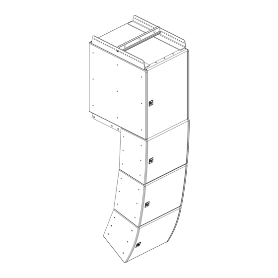
Shoulder Supplied Bolt Tie Plates Attach Tie Plates with (2 Supplied with M10 Bolts Supplied each EVA Module) EVA Module Grid Assembly Detail Note: Cosmetic End Figure 14: Panels Not Shown Typical EVA flying system Electro-Voice EVA Series User Manual... -
Page 24: Deciding Which Grid Configuration To Use With An Eva Array
When the standard grid with its single spreader bar is used, the down angle of the array is determined by the front-to-back attachment position of the spreader bar. This information is provided by Electro-Voice’s EVA Design Assistant (EVADA™), a function of the array makeup and desired vertical aiming. See section 3.0 Designing an EVA Array. -
Page 25: Extended Grid With Or Without Second Spreader Bar
Second (EVA-GXB) Extended (EVA-EG2) Spreader Bar Sidearm (Sold Separately) Figure 17: Spreader Bar Extended (EVA-EG2) EVA-EG2 extended grid (shown with Sidearm optional EVA-GXB spreader bar) EVA Module(s) (Not included with Grid) Electro-Voice EVA Series User Manual... -
Page 26: Coupler Grid With Or Without Second Spreader Bar
Figure 18: EVA-SG2 Standard Grid The use of EVA-CG coupler grid to array EVA-1151D’s behind EVA-2082S’s EVA Module(s) EVA-SG2 Standard Grid Figure 19: The use of two EVA-SG2 standard grids to achieve extreme down angles Electro-Voice EVA Series User Manual... -
Page 27: Eva-1151D Tie Plates
EVA-1151 to EVA-1151 Array, EVA-1151 to EVA-1151 Array, EVA-1151 to EVA-2082 Array, 0° Splay Between Enclosures 5° Splay Between Enclosures 0° Splay Between Enclosures Figure 20: EVA-1151D tie plate configurations (left side shown, right side mirrored) Electro-Voice EVA Series User Manual... -
Page 28: Assembling And Flying An Eva Array
Note that shading and/or attenuation in the wrong place will seriously detract from the performance of the completed array! The completed array may now be hoisted into position and secured in the final way intended. Electro-Voice EVA Series User Manual... -
Page 29: Rigging-Strength Ratings And Safety Factors
The working-load limits defined by the manufacturer of any rigging component should never be exceeded. Electro-Voice bases the working-load limits of its EVA products on a minimum of an 8:1 safety factor. Other manufacturers of rigging components may base their working-load limits on safety factors other than 8:1. -
Page 30: Structural-Rating Overview
To make EVA systems both safe and easy to use, Electro-Voice engineers have chosen to treat EVA arrays as a single unified structure rather than individual components. All the complex factors listed below have... -
Page 31: Simplified Structural-Rating Guidelines
FIVE and the maximum number of EVA-1151D subwoofer modules at the rear of the grid is THREE. A bottom pull-up is not allowed when using the EVA-CG. Flying a single col- umn from the EVA-CG is not allowed. Electro-Voice EVA Series User Manual... - Page 32 Side-to-side simplified structural-rating guide- Figure 23: lines for EVA arrays (angle shown exaggerated Front-to-back angular pull structural-rating for illustration purposes) guidelines for EVA spreader bars Figure 22: Side-to-side angular pull structural-rating guidelines for EVA spreader bars Electro-Voice EVA Series User Manual...
-
Page 33: Special Rules When Flying Eva-2151D Subwoofer Modules
OD THAN THE uSE Of EVA-SG2, EVA-EG2 Or EVA-CG GriDS AND SPrEADEr BArS AS OuTLiNED iN THiS MANuAL! EVA-1151D MODuLES MAy BE SuSPEND- ED frOM iNVErTED EVA-1151D TiE PLATES ONLy iN CONjuNCTiON WiTH AN EVA-GXB SPrEADEr BAr (SOLD SEPArATELy). Electro-Voice EVA Series User Manual... -
Page 34: Eva Structural Rating Charts
Angle not to exceed 45° down with bottom pull-up. 1 (Top) 2151D 2151D 2151D 2151D 2151D 2151D 2082S 2082S 2082S 2151D 2151D 2151D 2082S 2082S 2082S 2082S 2082S 2082S 2082S 2082S 2082S 2082S 2082S 2082S 2082S 2082S 2082S 2082S 2082S 2082S Electro-Voice EVA Series User Manual... - Page 35 MUST USE BOTH OUTER SUSPENSION POINTS ON Position SPREADER BAR(S) 1 (Top) 2151D 2151D 2151D 2151D 2151D 2151D 2151D 2151D 2151D 2151D 2151D 2151D 2151D 2151D 2151D 2151D 2151D 2151D 2151D 2151D 2151D 2151D 2151D 2151D 2151D 2151D Electro-Voice EVA Series User Manual...
-
Page 36: Electro-Voice Structural-Analysis Procedures
6.0 Rigging-Strength Ratings and Safety Factors (cont’) 6.6 Electro-Voice Structural-Analysis Procedures Electro-Voice maintains a structural pull-test facility in Burnsville, Minnesota USA which includes load cells with digital-electronic display and recording. The load cells are calibrated annually by an independent laboratory to a standard traceable to the United States National Bureau of Standards. This pull-test facility is capable of pulling to destruction both individual rigging components and complete loudspeaker sys- tems. -
Page 37: Rigging Inspection And Precautions
Hardware that is bent or showing signs of more than cosmetic surface corrosion should be replaced immediately. Electro-Voice EVA Grids: Prior to each use, inspect the grid side bars and spreader bars for any cracks, corrosion, missing or damaged parts or any other deformation that could reduce their strength and integ- rity. -
Page 38: References
[4] J.L. Meriam & L.G. Kraige, Engineering Mechanics, Volume Two - Dynamics, John Wiley & Sons, Inc., New york, Ny, USA (1992). [5] J.E. Shigley & C.R. Mischke, Mechanical Engineering Design, McGraw-Hill Book Company, New york, Ny, USA (1989). Electro-Voice EVA Series User Manual... -
Page 39: Rigging (Websites)
8.0 References (cont’) 8.3 rigging (Web sites) [1] http://www.rigging.net [2] http://www.cmworks.com/ [3] http://catalog.thecrosbygroup.com/maininterface.htm Notes Electro-Voice EVA Series User Manual... - Page 40 Other Internatonal locations. For customer orders, Contact Customer Service at: + 1 952 884-4051 fax: + 1 952 887-9212 www.electrovoice.com For warranty repair or service information, contact the Service Repair department at: Electro-Voice EVA Series User Manual 800/685-2606 © Bosch Communications Systems 02/2011...
Need help?
Do you have a question about the EVA-2082S/906EVA-2082S/920EVA-2082S/126 and is the answer not in the manual?
Questions and answers