Table of Contents

Related Manuals for Ace Heating Solutions Mini-Pack

Summary of Contents for Ace Heating Solutions Mini-Pack
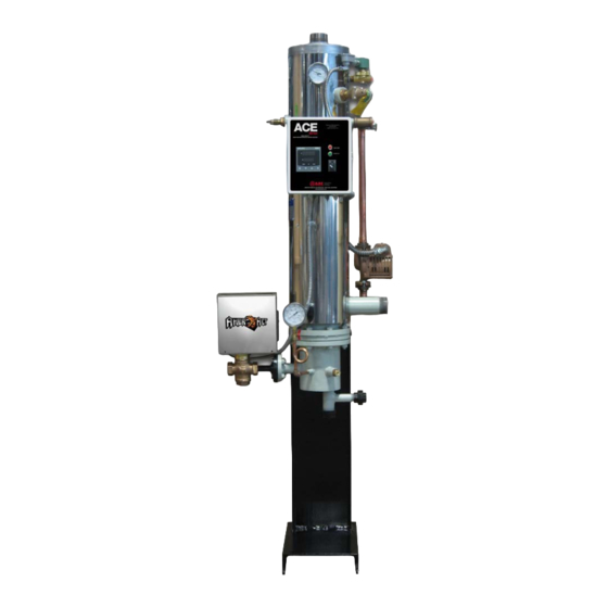
- Page 1 Electric “Mini-Pack” System Semi-Instantaneous Water Heater Steam-to-Water System Operating and Maintenance Manual Designed and Manufactured in Accordance with ASME Code Section VIII, Division Photo shown may vary from actual model.
-
Page 3: Table Of Contents
ACE BOILER INC. Page 2 Table of Contents Page Operating and Installation Instruction The Mini-Pack Name Plate and Model Number The Parts of the Boiler How it works Receiving your Mini-Pack General Installation Instruction 10 Installation Diagram Single-wall Double-wall 12 Before Start-up... -
Page 4: Operating And Installation Instruction
Mini-Pack for future reference. The Ace Boiler Mini-Pack is of rugged construction, yet of simple design. The heater uses steam (or water) from a boiler to heat domestic water. The Mini-Pack's temperature control system enables it to control the heated water within + 4qF of the selected temperature during normal operating conditions. -
Page 5: The Mini-Pack Nameplate And Model Number
ACE BOILER INC. Page 4 The Mini-Pack Nameplate And Model Number The Mini-Pack Nameplate The following illustration is an accurate depiction of the nameplate found on the mini-pack. NB or serial number Shell pressure C. Shell temperature D. Tube pressure... - Page 6 ACE BOILER INC. Page 5 Parts of the Mini-Pack...
-
Page 7: How It Works
Page 6 How It Works! The Mini-Pack is designed to heat domestic hot water using existing plant steam or hot boiler water, and regulates the domestic hot water outlet temperature to a close tolerance of +4qF from the set point. The advantage of this system is it replaces the need for large hot water storage tanks and is much more efficient. -
Page 8: Receiving Your Mini-Pack
“Bill of Lading”. Larger strainers, usually 2 ½ and above, are shipped loose. Note any damages or shortages on the bill of lading prior to signing it. If the Mini-Pack is received damaged or missing parts, it is your responsibility to notify the shipping company and file a freight claim. - Page 9 ACE BOILER INC. Page 8 Torque's: The following are recommended bolt torque requirements MP Size Bolt Gasket Compressed Min Torque Max Torque*** Size* Thickness** Thickness 4" 1/2" 1/4" 0.018" 45 ft.lb 60 ft.lb 5" 1/2" 1/4" 0.018" 45 ft.lb 60 ft.lb 6"...
- Page 10 Ace Boiler Inc. recommends consulting a water treatment specialist prior to start-up for recommendations on water treatment. The Mini-Pack uses boiler steam or hot water as its heating medium. On steam systems, boiler makeup water continuously introduces contaminants; scale forming solids, corrosive minerals and oxygen, which can cause corrosion or scale formation inside the Mini-Pack tube bundle.
-
Page 11: Installation Diagram
ACE BOILER INC. Page 10 Installation Diagram (Single-Wall) -
Page 12: Double-Wall
ACE BOILER INC. Page 11 Installation Diagram (Double-Wall) -
Page 13: Before Start-Up
Page 12 Before Start-up 1. Verify the Mini-Pack is installed in accordance with the appropriate installation diagram located on page 10 and 11. 2. The condensate outlet union has been factory installed with an orifice plate. Do not remove this orifice, as it acts as a simple steam trap, unless it is substituted with an appropriately sized stream trap. - Page 14 9. Manually open the main steam shut-off valve upstream of the control valve and SLOWLY allow steam to pass through the control valve. Continue until the shut-off valve is 100% open. 10. The Mini-Pack will now function automatically, reacting according to demand fluctuations and will stabilize once limits are met.
-
Page 15: Shut Down Instructions
The three-way valve also vents any air left in the actuator, thus ensuring full shut-off of the control valve. 3. The relief valve is designed to relieve the pressure in the Mini-Pack in the event the pressure gets too high. -
Page 16: Trouble Shooting
ACE BOILER INC. Page 15 Trouble Shooting 1. Water temperature too high: 1. Check the setting of the Accritem and its sensitivity screw (and positioner if provided), and verify a steady 30 PSI air supply pressure to the Accritem. The outlet pressure gauge on the Accritem should read 30 PSI when fully opened, and 0 PSI when fully closed. - Page 17 2. Confirm steam supply pressure to the control valve meets that specified in the List of Materials. Check for a clogged strainer, a partially closed supply valve or other obstructions. 3. Make sure the Mini-Pack is not trying to supply more hot water than it was designed for (See performance listed in List of Materials enclosed).
-
Page 18: Maintenance Instruction
RELIEF VALVE: The Mini-Pack is equipped with a lever type relief valve of “ASME” rated capacity. To maintain the valve in good working condition, it should be manually opened once a month. The relief valve outlet should be piped directly to an open drain and the drain checked frequently for discharge. -
Page 19: Mini-Pack Component Weights
ACE BOILER INC. Page 18 Mini-Pack Component Weights Single-wall units Double-wall units Coil Weight Bonnet Shell Coil Bonnet Shell Size Weight Weight Size Weight Weight Weight 5" 125 lbs. 40 lbs. 95 lbs. 4" 30 lbs. 30 lbs. 60 lbs. -
Page 20: Tube Bundle And Bonnet Installation
ACE BOILER INC. Page 19 4. Complete the seal by crossing the ends near a bolt hole. Cross one end over the other about 1" and cut (as shown in VIEW "B"). VIEW "B" 5. Assemble the flanged joints and torque the bolts as follows. a) Run up all the nuts, finger tight. - Page 21 ACE BOILER INC. Page 20 3. Install heat exchanger bundle: Bundle should be lifted or jacked with care as to not damage the tubes or tube sheet gasket surface. Lift the bundle to the proper height prior to tightening nuts down.
-
Page 22: Preventive Maintenance
3. Check ALL operating components for proper functionality. Check all electrical connections. Replacement Parts Ace Boiler maintains a complete equipment list for each Mini-Pack, filed by serial number. In order for us to give prompt service and to ensure that correct parts are supplied, please be sure and supply the model and serial number. - Page 23 3. Ace Heating Solutions, LLC do not provide a warranty or guarantee, express or implied, in any manner, form, usage of trade, 3. Ajax Boiler Inc. do not provide a warranty or guarantee, express or implied, in any manner, form, usage of trade, merchant merchantability or fitness which extend beyond the product description and quotation.
- Page 24 The liability of Ace Heating Solutions, LLC. is limited solely to the replacement of the complete pressure vessel, with tubes, if found by our inspection to be damaged by thermal shock. In no event shall Ace Heating Solutions, LLC. be held liable for replacement labor charges or for freight or handling charges.
- Page 25 This warranty is limited to the above and applies only for the period set forth. Ace Heating Solutions, LLC This warranty is limited to the above and applies only for the period set forth. Ajax Boiler Inc. will not be liable for any loss...
- Page 26 Ace Heating Solutions, LLC OILER OILER ARNING PRODUCT SAFETY NOTICE ACE BOILER AND WATER HEATER PRODUCTS OPERATE AT HIGH TEMPERATURE AND PRESSURES AJAX BOILER AND WATER HEATER PRODUCTS OPERATE AT HIGH TEMPERATURE AND PRESSURES • Before using this product, read and understand instructions. Save these instructions for future use.
- Page 27 CONTROL PANEL OPERATING PROCEDURES INTRODUCTION The information in this Chapter provides a guide to the operation of the ACE Mini-Pack Semi- instantaneous Water Heater with electric valve. The Control Panel is mounted on the front of the unit. It is imperative that the initial startup of this unit be performed by factory trained personnel.
- Page 28 OPERATION All the data from the PID Modulation Controller is displayed on two lines of seven segments LED display. The display has three main zones: 1. PV Display: Current outlet temperature (PV) or parameter type is shown depending on the function of the screen.
- Page 29 Upper Display Lower Display Description PV – Outlet SV – Setpoint Displays current and Setpoint temperature. This is Temperature the initial screen of Operation Mode. PV – Outlet OUTPUT – Lower display shows modulation output in Temperature Modulation Output percentage. In this screen modulation output can be switched from auto to manual and vice versa by pressing the key for three seconds.
- Page 30 Upper Display Lower Display Description PArA Setup Mode initial screen Key lock setting 20.0 Output proportional band setting 20.0 Output integral time Output derivative time Output manual reset 0.40 Output target value function * o_L * 0.0 or 20.0 Output lower limit Units with Siemens Valve –...
- Page 31 When AT is executed, control operates in ON-OFF mode Output response is used to calculate new PID parameter. When auto tuning is completed, new PID value is stored, auto tuning ends and AT lamp goes off. Stop Auto Tuning To stop auto tuning in the middle of execution, select OFF by using the button on the auto tuning.
- Page 32 Lock Description Setting Locks up all Setup Mode parameters. Locks up all Setup Mode parameters and all Operation Mode parameters except the initial screen of Operation Mode. Only setpoint parameter can be adjusted. Locks up all the parameters. No lock, any data can be changed. Table 3 –...
- Page 83 ➤ ➤ ➤ ➤ ➤...
- Page 100 Model No. www.aceheatingllc.com Ace Heating Solutions, LLC. All rights reserved. Printed in the USA Performance specifications are effective with date of issue and are subject to change without prior notice. The brand and product names contained within this document are trademarks or registered of their respective holders.
Need help?
Do you have a question about the Mini-Pack and is the answer not in the manual?
Questions and answers