
Related Manuals for Body Rider BRF 700


Summary of Contents for Body Rider BRF 700
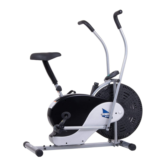
- Page 1 BRF 700 BRF 701 Fan Bike * This item is for consumer use only and it is not meant for commercial use. OW N ER ’ S M ANUAL...
-
Page 2: General Information
21717 Ferrero Parkway, Walnut, CA 91789 - 1 x Philips (”Crosshead”) Screw Driver Telephone: (888) 266 - 6789 Weight Limit Fax: (909) 598 - 6707 Email: info@bodyflexsports.com Your product is suitable for users weighing: 250 pounds or less. BRF 700/701 Page 1... -
Page 3: Hardware List
The following hardware is used to assemble your unit. Please take a moment to familiarize yourself with these items. Please note some of this hardware is already pre-assembled on the machine. Do not be alarmed if you see parts on this page that are not included in your hardware packet S10-S13-S15-S17-S19 [1 piece] Page 2 BRF 700/701... -
Page 4: Parts Listing
Bolt (M10x18 mm) Friction Belt Spring Washer (M10) Bushing D Shape Washer (M10) Foam Grip Handlebar Axle Knob (M12) Round Cap (25) Bolt (M8x43 mm) Washer (M8) Nylon Nut (M8) BRF 700/701 Page 3 BRM 3670 Stride Cycle Page ? -
Page 5: Exploded Diagram
Please continue to the next page to begin the assembly process and use this page only as a reference guide for parts and hardware. BRF 700/701 Page 4... -
Page 6: Assembly Instructions
A s s e m b l y S t e p 1 Secure the Front Stabilizer (#2A)to the Main Frame (#1A) with two Carriage Bolts (#26), two Arc Washers (#27) and two Cap Nuts (#28). BRF 700/701 Page 5... - Page 7 Hardware Required A s s e m b l y S t e p 2 Secure the Rear Stabilizer (#3) to the Main Frame (#1A) with four Bolts (#24), four Spring Washers (#25) and four Washers (#19). BRF 700/701 Page 6...
- Page 8 Right Hand Side: Turn CLOCKWISE to tighten the Right Pedal • (#7R) on the right crank. Then turn COUNTERCLOCKWISE to tighten the Right Nylon Nut (#23R) [WHITE inner nylon ring] to secure the right pedal assembly. Right Crank BRF 700/701 Page 7...
-
Page 9: Please Note
Big Washer (#21) and the two pieces fit flushed together. Please refer to the exploded diagram for correct flushed together. Please refer to the exploded diagram for correct orientation and positioning. orientation and positioning. BRF 700/701 Page 8... - Page 10 Then attach the Right Handlebar (#4R) to the Right Linkage (#6R) with a Washer (#19) in the between, secure with a Bolt (#18), a Washer (#19) and a Nylon Nut (#20). Repeat this process on the left side**. BRF 700/701 Page 9...
- Page 11 Nylon Nut (#20) > Washer (#19) > Right Linkage (#6L) > Washer (#19) > Left Handlebar (#4L) (#6R) > Washer (#19) > Right Handlebar (#4R) > Bolt (#18) > Bolt (#18) *RIGHT Side: **LEFT Side: INNER (SIDE) OUTTER (SIDE) OUTTER (SIDE) INNER (SIDE) BRF 700/701 Page 10...
- Page 12 Please refer to the illustration below. Always ensure that the Knob (#17) is securely tightened and engaged through the hole on the Main Frame (#1A) and the hole setting most comfortable to you on the Seat Tube (#5A) for your safety. Page 11 BRF 700/701...
- Page 13 Owner’s Manual which includes safety instructions and warnings, as well as any safety/warning labels affixed to the product before use. For your safety, please visually and functionally inspect and test the unit after assembly is complete. Page 12 BRF 700/701...
- Page 14 The more length you allow for the friction belt to wrap around the wheel, the less friction it will cause. Re-adjust the tension knob after you finished re-strapping. BRF 700/701 Page 13...
-
Page 15: Safety And Maintenance
(909) 598-9876, or mail in a written request to: Body Flex Sports, Inc. 21717 Ferrero Parkway, Walnut, CA 91789. More detailed information about how to reach our CUSTOMER SUPPORT may be found on Page 1 of the Owner’s Manual under the “CUSTOMER SUPPORT” section. Page 14 BRF 700/701... -
Page 16: Computer Operation
The computer is intended only as an exercise aid to track relative progress when using the corresponding exercise unit. Page 15 BRF 700/701... - Page 17 5. ALWAYS use your Equipment in a warm, dry, level well-lit and ventilated 11. NEVER use the Equipment if it does indoor area. not function properly. 6. ALWAYS keep body and clothing free and clear of all moving parts. BRF 700/701 Page 16...
- Page 18 This page intentionally left blank...
-
Page 19: Proof Of Purchase
Proof of purchase Model Number BRF700/701 version: 05-1 -2013 BRF 700/701... - Page 20 Body Flex Sports, Inc. • 21717 Ferrero Parkway, Walnut, CA 91789 • Telephone: (888) 266 - 6789 • Email: info@bodyflexsports.com...
Need help?
Do you have a question about the BRF 700 and is the answer not in the manual?
Questions and answers
How do I order replacement parts?
What is the actual seat size so I can buy a seat cover with cushion
The pedals turn easily going backwards, but are extremely difficult going forward. The tension adjustment is not the issue. How do I correct this.