
Related Manuals for Body Rider BRF 701


Summary of Contents for Body Rider BRF 701
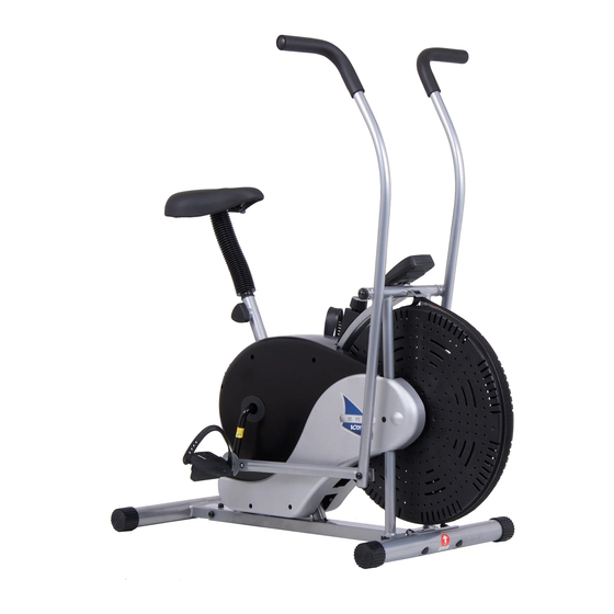
- Page 1 BRF 700 BRF 701 Fan Bike * This item is for consumer use only and it is not meant for commercial use. OW N ER ’ S M ANUAL...
- Page 2 This page intentionally left blank...
-
Page 3: General Information
Warranty this manual carefully before commencing the assembly of your product or starting to Body Flex Sports warrants your product for exercise. a period of 1 year for the frame and 90 days on all parts if the item is used for the intended •... -
Page 4: Hardware List
Hardware List The following hardware is used to assemble your unit. Please take a moment to familiarize yourself with these items. Please note some of this hardware is already pre-assembled on the machine. Do not be alarmed if you see parts on this page that are not included in your hardware packet S10-S13-S15-S17-S19 [1 piece] Page 2... -
Page 5: Parts Listing
Parts Listing The following parts list describes all of the parts illustrated on the exploded diagram on the following page. Please note, most of these parts are already pre-assembled on your unit. Description Description Main Frame Big Washer Front Stabilizer Bushing Rear Stabilizer 23L Left Nylon Nut... -
Page 6: Exploded Diagram
Exploded Diagram The following diagram is provided to help you familiarize yourself with the parts and hardware that will be used during the assembly process. Please note that not all of the parts and hardware you see here will be used while you are assembling the machine because some of these items are already pre-installed. -
Page 7: Assembly Instructions
Assembly Instructions A s s e m b l y S t e p 1 Hardware Required Secure the Front Stabilizer (#2A)to the Main Frame (#1A) with two Carriage Bolts (#26), two Arc Washers (#27) and two Cap Nuts (#28). BRF 700/701 Page 5... - Page 8 Assembly Instructions A s s e m b l y S t e p 2 Hardware Required Secure the Rear Stabilizer (#3) to the Main Frame (#1A) with four Bolts (#24), four Spring Washers (#25) and four Washers (#19). BRF 700/701 Page 6...
- Page 9 Assembly Instructions A s s e m b l y S t e p 3 Hardware Required Attach the Right Pedal (#7R) to the Right Linkage (#6R) with a Bushing (#22) and a Big Washer (#21) in between. Then screw the Right Pedal (#7R) tightly into the right crank and then secure it with the Right Nylon Nut (#23R).
- Page 10 Assembly Instructions A s s e m b l y S t e p 4 Hardware Required Remove the two Special Washers (#29), two D Shape washers (#15), two Spring Washers (#14) and two Bolts (#13) that are pre-assembled on the Handlebar Axle (#16). Insert the Handlebar Axle (#16) through the Main Frame (#1A).
- Page 11 Assembly Instructions A s s e m b l y S t e p 5 Hardware Required Remove the three Washers (#10) and three Nuts (#11) that are pre-assembled on the Seat (#9). Then attach the Seat (#9) to the Seat Tube (#5A) and secure it with three Washers (#10) and three Nuts (#11) that were previously removed.
- Page 12 Assembly Instructions A s s e m b l y S t e p 6 Hardware Required Attach the Monitor (#8) to the Main Frame (#1A) and then connect the Monitor Wire (#37A) to the Monitor Wire (#37B). The assembly of fan bike is now complete. BRF 700/701 Page 10...
- Page 13 Assembly Instructions Tension Adjustment For slight tension adjustment, simply turn the tension adjustment knob found at the top center. Tension level can be manipulated this way to vary intensity of workout as you exercise. For greater tension adjustment, you may loosen or tighten the Friction Belt (#38) by re-strapping it. To do so, first turn the tension adjustment knob all the way to the loosest setting.
-
Page 14: Computer Operation
Computer Operation SPECIFICATIONS: TIME………………………………………0:00-99:59 SPEED……………………………………0.0-99ML/H DISTANCE ……………………………0.0-999.9ML CALORIES………………………………0.0-9999CAL KEY FUNCTION: MODE: This key lets you to select and lock on to a particular function you want. OPERATION PROCEDURES: 1. AUTO ON/OFF: ◆ The system turns on when any key is depressed of when it receives an input from the speed sensor. -
Page 15: Proof Of Purchase
Proof of purchase Model Number BRF700/701 version: 3-3-2011 V2 BRF 700/701 Page 13... - Page 16 Body Flex Sports, Inc. • 21717 Ferrero Parkway, Walnut, CA 91789 • Telephone: (888) 266 - 6789 • Email: info@bodyflexsports.com...
Need help?
Do you have a question about the BRF 701 and is the answer not in the manual?
Questions and answers
The chain is hanging from under the bike pedal also will not turn How do I get the chain back on