
Related Manuals for Body Rider XRB271


Summary of Contents for Body Rider XRB271
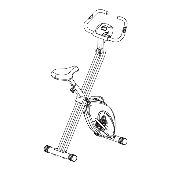
- Page 1 Deluxe Folding Bike XRB271 / XRB261 * This item is for consumer use only and it is not meant for commercial use. OW NER’S MA NUAL...
-
Page 2: General Information
21717 Ferrero Parkway, Walnut, CA 91789 - 1 x Philips (”Crosshead”) Screw Driver Telephone: (888) 266 - 6789 Weight Limit Fax: (909) 598 - 6707 Email: info@bodyflexsports.com Your product is suitable for users weighing: 250 pounds or less. XRB271 Page 1... -
Page 3: Hardware List
Hardware List The following hardware is used to assemble your unit. Please take a moment to familiarize yourself with these items. Please note some of this hardware is already pre-assembled on the machine. Do not be alarmed if you see parts on this page that are not included in your hardware packet Bolt #17. -
Page 4: Parts Listing
Parts Listing The following parts list describes all of the parts illustrated on the exploded diagram on the following page. Please note, most of these parts are already pre-assembled on your unit. Part# Description Part# Description Shroud Frame Arc Washer (M6) Main Frame Nylon Nut (M8) Seat Post... -
Page 5: Exploded Diagram
Exploded Diagram The following diagram is provided to help you familiarize yourself with the parts and hardware that will be used during the assembly process. Please note that not all of the parts and hardware you see here will be used while you are assembling the machine because some of these items are already pre-installed. -
Page 6: Assembly Instructions
Assembly Instructions A s s e m b l y S t e p 1 A.) Remove the Pop Pin (#15) that is pre-assembled through the lower hole of the Shroud Frame (#01). Then, insert it into the upper hole located on the Shroud Frame (#01) until it passes through and clicks into place. For your safety, this Pop Pin (#15) MUST remain inserted whenever the unit is in use OR if it is left unfolded and/or unattended. - Page 7 Assembly Instructions A s s e m b l y S t e p 2 A.Secure Left Pedal (#08) onto the Left Crank (#06) by turning it COUNTER-CLOCKWISE. You will need to use a Wrench to tighten if necessary. B.Secure Right Pedal (#09) onto the Right Crank (#07) by turning it CLOCKWISE. You will need to use a Wrench to tighten if necessary.
- Page 8 Assembly Instructions A s s e m b l y S t e p 3 Remove the Washers (#25) and Nylon Nuts (#29) that are pre-assembled on the Seat (#11), and set them aside for now. Attach the Seat (#11) to the Seat Post (#03) using a total of three Washers (25) and three Nylon Nuts (#29) that were previously removed and set aside.
- Page 9 Assembly Instructions A s s e m b l y S t e p 4 A.) Attach Handlebar (#04) to the Main Frame (#02), AND secure them together by using two Bolts (#17), two Spring Washers (#26) and two Washers (#22) from the sides, and two Bolts (#17), two Spring Washers (#26) and two Arc Washers (#28) from the front.
-
Page 10: Safety Instructions
Safety Instructions / Computer Operation SAFETY INSTRUCTIONS • Make sure all nuts/bolts are securely (but not over) tightened. • Check for loose parts and components prior to each use. • Check to see if there are any tears or bends in the welding or metal. Do NOT use the unit if any are present. - Page 11 Thanks for choosing XRB 271 Store Location: version: 2-10-2012 XRB 271...
- Page 12 Body Flex Sports, Inc. • 21717 Ferrero Parkway, Walnut, CA 91789 • Telephone: (888) 266 - 6789 • Email: info@bodyflexsports.com...
Need help?
Do you have a question about the XRB271 and is the answer not in the manual?
Questions and answers