Table of Contents
Advertisement
Available languages
Available languages
Safe Operation Practices • Set-Up • Operation • Maintenance • Service • Troubleshooting • Warranty
O
'
M
peratOr
s
anual
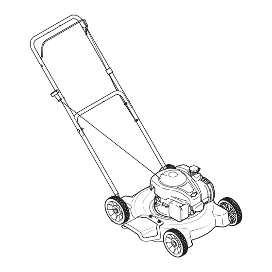
Push Mower — Model Series 020
WARNING
READ AND FOLLOW ALL SAFETY RULES AND INSTRUCTIONS IN THIS MANUAL
BEFORE ATTEMPTING TO OPERATE THIS MACHINE.
FAILURE TO COMPLY WITH THESE INSTRUCTIONS MAY RESULT IN PERSONAL INJURY.
MTD LLC, P.O. BOX 361131 CLEVELAND, OHIO 44136-0019
Printed In USA
Form No. 769-09189
(October 14, 2013)
Advertisement
Table of Contents

Subscribe to Our Youtube Channel
Related Manuals for MTD 020 Seies


Summary of Contents for MTD 020 Seies
- Page 1 READ AND FOLLOW ALL SAFETY RULES AND INSTRUCTIONS IN THIS MANUAL BEFORE ATTEMPTING TO OPERATE THIS MACHINE. FAILURE TO COMPLY WITH THESE INSTRUCTIONS MAY RESULT IN PERSONAL INJURY. MTD LLC, P.O. BOX 361131 CLEVELAND, OHIO 44136-0019 Printed In USA Form No. 769-09189...
-
Page 2: Table Of Contents
Visit us on the web at www.mtdproducts..com See How-to Maintenance and Parts Installation Videos at www.mtdparts.com/KnowledgeCenter ◊ Call a Customer Support Representative at (800) 800-7310 or (330) 220-4683 ◊ Write to MTD LLC • P.O. Box 361131 • Cleveland, OH • 44136-0019... -
Page 3: Important Safe Operation Practices
Important Safe Operation Practices WARNING: This symbol points out important safety instructions which, if not followed, could endanger the personal safety and/or property of yourself and others. Read and follow all instructions in this manual before attempting to operate this machine. Failure to comply with these instructions may result in personal injury. - Page 4 A missing or damaged discharge cover can cause blade When starting engine, pull cord slowly until resistance contact or thrown object injuries. is felt, then pull rapidly. Rapid retraction of starter cord (kickback) will pull hand and arm toward engine faster than Many injuries occur as a result of the mower being pulled you can let go.
- Page 5 Service Check the blade and engine mounting bolts at frequent intervals for proper tightness. Also, visually inspect blade Safe Handling Of Gasoline: for damage (e.g., bent, cracked, worn) Replace blade with the original equipment manufacture’s (O.E.M.) blade only, To avoid personal injury or property damage use extreme listed in this manual.
-
Page 6: Spark Arrestor
Notice Regarding Emissions Spark Arrestor Engines which are certified to comply with California and federal WARNING: This machine is equipped with an EPA emission regulations for SORE (Small Off Road Equipment) internal combustion engine and should not be used are certified to operate on regular unleaded gasoline, and on or near any unimproved forest-covered, brush may include the following emission control systems: Engine covered or grass-covered land unless the engine’s... -
Page 7: Safety Symbols
Safety Symbols This page depicts and describes safety symbols that may appear on this product. Read, understand, and follow all instructions on the machine before attempting to assemble and operate. Symbol Description READ THE OPERATOR’S MANUAL(S) Read, understand, and follow all instructions in the manual(s) before attempting to assemble and operate DANGER —... - Page 8 2 — i ection mportant peration racticeS...
-
Page 9: Assembly & Set-Up
Assembly & Set-Up Contents of Carton • One Lawn Mower • One Lawn Mower Operator’s Manual • One Engine Operator’s Manual • One Hardware Pack • Four Wheels • One Upper & Lower Handle • One Blade Control • One Chute Deflector •... -
Page 10: Tools Required
Tools Required • 7⁄16-inch wrench (or adjustable wrench) • 1⁄2-inch wrench (or adjustable wrench) • 9⁄16-inch wrench (or adjustable wrench) • 3⁄4-inch wrench (or adjustable wrench) Flange Lock Nut Assembly Shoulder Screw NOTE: This lawn mower is shipped without gasoline or oil in the engine. - Page 11 Wheels Straight NOTE: Use the hardware in Group 3 to complete the following steps. The holes in the deck provide three cutting heights. Use corresponding holes when attaching all four wheels (i.e. for the Curved lowest cutting position, assemble each wheel at the highest hole on the deck).
- Page 12 NOTE: Your mower has been supplied with one of two types of control cables - one that is secured with a snap fitting as shown in Figure 3-7 or one that is secured with a stud as shown in Fig.3- 8.
-
Page 13: Starter Rope
Z Fitting Attach the eye bolt to the upper handle and loosely thread the lock nut on to secure it. Do NOT tighten. See Figure NOTE: Use the hardware in Group 6 to complete the following 3-10 . steps. With the spark plug wire disconnected and grounded, To make it easier to attach the Z fitting, temporarily remove depress the blade control and pull the rope out of the the left side of the blade control as shown in Figure 3-9. -
Page 14: Controls & Features
Controls and Features Blade Control Recoil Starter Primer Figure 4-1 Primer Blade Control The primer is located on the left side of the The blade control is attached to the upper handle of the mower. engine. The primer is used to pump gas into Depress and squeeze it against the upper handle to operate the the carburetor and aid in starting the engine. -
Page 15: Operation
Operation Starting Engine WARNING: Be sure no one other than the operator is standing near the lawn mower while starting engine or operating mower. Never run engine indoors or in enclosed, poorly ventilated areas. Engine exhaust contains carbon monoxide, an odorless and deadly gas. -
Page 16: Maintenance & Adjustment
Maintenance & Adjustments Maintenance Deck Care Clean underside of the mower deck after each use to prevent General Recommendations build-up of grass clippings or other debris. Follow steps below • Always observe safety rules when performing any for this job. maintenance. -
Page 17: Service
Service Blade Care WARNING: An unbalanced blade will cause excessive vibration when rotating at high speeds. It WARNING: When removing the cutting blade for may cause damage to mower and could break sharpening or replacement, protect your hands with causing personal injury. a pair of heavy gloves or use a heavy rag to hold the Lubricate the engine crankshaft and the inner surface of blade. -
Page 18: Troubleshooting
Troubleshooting Problem Cause Remedy Engine Fails to start 1. Blade control disengaged. 1. Engage blade control. 2. Spark plug boot disconnected. 2. Connect wire to spark boot. 3. Fuel tank empty or stale fuel. 3. Fill tank with clean, fresh gasoline. 4. -
Page 19: Replacement Parts
Air Cleaner (MTD - 140cc Foam) 951-14628 Air Cleaner (MTD - 140cc Paper) 951-10732 Air Cleaner (MTD - 139cc Oval) 951-10298 Air Cleaner Kit (MTD - 139cc Square) BS-799585 Fuel Tank Cap (Briggs & Stratton) 951-12738 Fuel Cap Assembly (MTD) 951-10358A... -
Page 20: Attachments & Accessories
Attachments & Accessories Component Model Number and Description 490-850-0005 Blade Removal Tool — Holds blade in place for faster, safer removal. SPW-134 Spark Plug Wrench — Duel ended wrench to serve multiple uses. Fits ¾” or 13⁄16” hex plug. 490-850-0008 Oil Siphon —... - Page 21 Component Model Number and Description 22216 STA-BIL® fuel Stabilizer, 32 oz — Treats 80 gallons of fuel. Keeps stored fuel fresh for quick, easy starts. Prevents corrosion from moisture and ethanol-induced attraction. Prevents gum and varnish. 490-290-0012 Mower Cover — Protects your mower against sun, rain and dust damage.
-
Page 22: Warranty
MANUFACTURER’S LIMITED WARRANTY FOR The limited warranty set forth below is given by MTD LLC with Log splitter pumps, valves, and cylinders have a separate respect to new merchandise purchased and used in the United one- year warranty. States and/or its territories and possessions, and by MTD Products... -
Page 23: Spanish
LEA Y SIGA TODAS LAS INSTRUCCIONES DE ESTE MANUAL ANTES DE PONER EN FUNCIONAMIENTO ESTA MÁQUINA. SI NO RESPETA ESTAS INSTRUCCIONES PUEDE PROVOCAR LESIONES PERSONALES. MTD LLC, P.O. BOX 361131 CLEVELAND, OHIO 44136-0019 Impreso en Estados Unidos de América Formulario No. 769-09189... - Page 24 Los números de teléfono, dirección cuidadosamente y en todo momento las prácticas de seguridad del sitio web y dirección postal de la Asistencia al Cliente de MTD recomendadas, y hacérselas seguir a cualquier otra persona que se encuentran en esta página. Queremos garantizar su entera opere la máquina.
- Page 25 Medidas importantes de seguridad ADVERTENCIA: La presencia de este símbolo indica que se trata de instrucciones importantes de seguridad que se deben respetar para evitar poner en peligro su seguridad personal y/o material y la de otras personas. Lea y siga todas las instrucciones de este manual antes de poner en funcionamiento esta máquina.
- Page 26 No ponga las manos o los pies cerca de las piezas rotatorias Nunca opere la cortadora sin las guardas apropiadas, o en la tolva de la cortadora. El contacto con las cuchillas cubierta de descarga, guarda para recorte, manija de puede producir la amputación de manos y pies.
- Page 27 Niños Nunca saque la tapa del gas ni agregue combustible mientras el motor está caliente o en marcha. Deje que el Pueden ocurrir accidentes trágicos si el operador no está atento motor se enfríe por lo menos dos minutos antes de volver a a la presencia de niños.
- Page 28 No modifique el motor Nunca trate de ajustar una rueda o la altura de corte mientras el motor está en marcha. Para evitar lesiones graves o la muerte, no modifique el motor Los componentes de la tolva para recorte, cubierta bajo ninguna circunstancia.
- Page 29 Símbolos De Seguridad Esta página representa y describe la seguridad los símbolos que pueden parecer en este producto. Lea, comprenda, y siga todas instrucciones de la máquina antes de intentar ensamblar y operar. Símbolo Descripción LEA EL MANUAL(S) DEL OPERADOR Lea, comprenda, y siga todas instrucciones en el manual (manuales) antes de operar el producto.
- Page 30 2 — M ección edidaS iMportanteS de Seguridad...
- Page 31 Montaje y Configuración Contenido de la caja • Una Podadora • Uno Manual de Operador • Uno Manual de Operador de Motor • Uno Paquete de Hardware • Uno Deflector del Canal • Uno Manija Superior & Inferior • Uno Control de la Cuchilla •...
- Page 32 Montaje Fije la manija inferior a la plataforma con los tornillos hexagonales, los tornillos con reborde y las tuercas de NOTA: Esta unidad se envía sin gasolina ni aceite en el motor. seguridad con brida. Vea Figura 3-2. Llene con gasolina y aceite como se indica en las instrucciones que se incluyen en el manual de motor adjunto ANTES de poner en funcionamiento su podadora.
- Page 33 Ruedas Extremo NOTA: Use los elementos de ferretería del Grupo 3 para recto completar los pasos siguientes. Los orificios en la plataforma proporcionan tres alturas de corte. Extremo Use los orificios correspondientes al colocar las cuatro ruedas (es curvo decir, para la posición de corte más baja, coloque cada rueda en el orificio más alto de la plataforma).
- Page 34 Ajuste el cable a la manija izquierda inferior con una unión de cable. Recorte el exceso de longitud de la unión de Control de la Cuchilla cable. Cable de Control (Perno) Manija superior Desenrolle el cable del motor por debajo de la manija inferior. Colocación del cable de Control NOTA: Use los elementos de ferretería del Grupo 6 para completar los pasos siguientes.
- Page 35 Con el cable de la bujía desconectado y colocado a masa, apriete el control de la cuchilla y jale la cuerda de arranque Control de la Cuchilla hacia afuera del motor. Enganche la cuerda a través del perno de ojo. Vea Figura 3-10.
- Page 36 Controles Y Características Control de cuchilla Arrancador de retroceso Cebador Figura 4-1 Control de Cuchilla Cebador El control de la cuchilla está unido a la manija superior. Presione El cebador se encuentra en el lado izquierdo la manija de control de la cuchilla contra la manija superior para del motor.
- Page 37 Funcionamiento Encendido del Motor ADVERTENCIA: Asegúrese que ninguna persona aparte del operador permanezca cerca de la podadora mientras arranca el motor u opera la misma. Nunca encienda un motor en espacios cerrados o en una zona con poca ventilación. El escape del motor contiene monóxido de carbono, un gas inodoro y letal.
- Page 38 Mantenimiento Y Ajustes Mantenimiento Siga el manual adjunto del motor para conocer las instrucciones y el programa de lubricación del mismo. Recomendaciones Generales Cuidado de la cubierta • Respete siempre las reglas de seguridad cuando realice Debe limpiar la parte inferior de la plataforma de la podadora tareas de mantenimiento.
- Page 39 Servicio Cuidado de la Cuchilla Lubrique el cigüeñal del motor y la superficie interna del adaptador de la cuchilla con aceite ligero. Deslice el ADVERTENCIA: adaptador de la cuchilla sobre el cigüeñal del motor. Instale Cuando saque la cuchilla de corte para afilarla o reemplazarla, protéjase las manos la cuchilla con el lado marcado “Bottom”...
- Page 40 Solución de problemas Problema Causa Remedio El motor no arranca 1. El control de lámina se retiró. 1. Contratar el control de lámina. 2. Alambre de bujía desconectado. 2. Unir el alambre a la bujía. 3. Depósito de combustible combustible vacío 3.
- Page 41 Problema Causa Remedio Demasiada vibración 1. Cuchilla floja o desequilibrada. 1. Apriete la cuchilla y el adaptador. Equilibre la cuchilla. 2. Cuchilla abollada. 2. Consulte a un distribuidor autorizado. La podadora no abona 1. Césped húmedo. 1. No corte el césped cuando está mojado, el césped espere hasta que sea más tarde para hacerlo.
- Page 42 Notas...
- Page 43 9 — n ection otaS...
- Page 44 Las disposiciones incluidas en esta garantía proveen el antideslizantes, ruedas de fricción, placas de raspado, gomas recurso único y exclusivo que surge de las ventas. MTD no será helicoidales, aceite de motor, filtros de aire, bujías y neumáticos. responsable por pérdidas o daños incidentales o directos, Accesorios —...
Need help?
Do you have a question about the 020 Seies and is the answer not in the manual?
Questions and answers