Table of Contents
Advertisement
SERVICE MANUAL
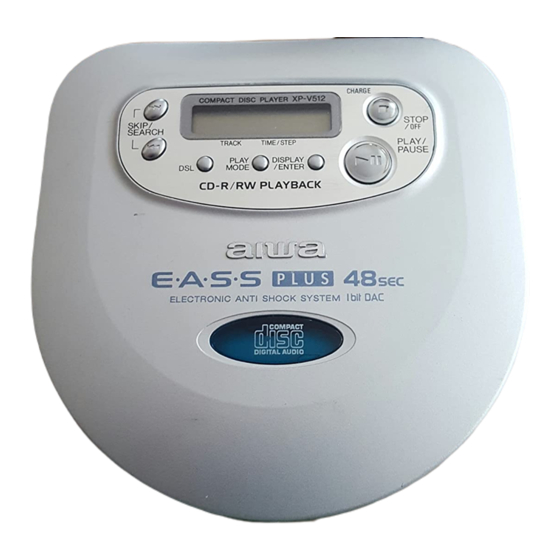
COMPACT DISC PLAYER
MODEL
XP-V510
XP-V511
XP-V512
XP-V513
XP-V514
• This Service Manual is the "Revision Publishing" and replaces "Simple Manual"
XP-V510(Y), XP-V511(AEZ), XP-V512(AEZ,AHK), XP-V513(AEZ,AK) and
XP-V514(AHC,AHR), (S/M Code No. 09-003-423-6T3).
XP-V510
XP-V511
XP-V512
XP-V513
XP-V514
BASIC CD MECHANISM : DA23L
Y1SF
AEZ1SF, AEZ1GF
AEZ1SF, AEZ1GF, AHKJ1LLF, AHKJ1SF
AEZ1VF, AK1VF
AHC1SF, AHR1GF, AHR1SF
S/M Code No. 09-003-423-6R2
TYPE
Y
AEZ
AEZ, AHK
AEZ, AK
AHC, AHR
Advertisement
Table of Contents

Subscribe to Our Youtube Channel
Related Manuals for Aiwa XP-V510


Summary of Contents for Aiwa XP-V510
- Page 1 AEZ1SF, AEZ1GF XP-V512 AEZ1SF, AEZ1GF, AHKJ1LLF, AHKJ1SF XP-V513 AEZ1VF, AK1VF XP-V514 AHC1SF, AHR1GF, AHR1SF • This Service Manual is the "Revision Publishing" and replaces "Simple Manual" XP-V510(Y), XP-V511(AEZ), XP-V512(AEZ,AHK), XP-V513(AEZ,AK) and XP-V514(AHC,AHR), (S/M Code No. 09-003-423-6T3). S/M Code No. 09-003-423-6R2...
-
Page 2: Specifications
SPECIFICATIONS <510Y, 511AEZ, 512AEZ, 513AEZ, 513AK> Tracking system: 3-beam laser Laser pickup: Semiconductor laser D/A conversion: 4-times oversampling digital filter + 1-bit DAC Frequency response: 20 - 20,000 Hz Output: PHONES / LINE OUT jack (stereo mini-jack) Maximum output: 10 mW + 10 mW (EIAJ 16 ohms at 1 kHz) 500 mV (47 kohms at 1 kHz) Power supply: DC 3 V using two LR6 (size AA) alkaline... -
Page 3: Protection Of Eyes From Laser Beam During Servicing
PROTECTION OF EYES FROM LASER BEAM DURING SERVICING This set employs laser. Therefore, be sure to follow carefully the CAUTION instructions below when servicing. Use of controls or adjustments or performance of procedures other than those specified herein may result in hazardous WARNING! radiation exposure. - Page 4 ELECTRICAL MAIN PARTS LIST REF. NO. PART NO. KANRI DESCRIPTION REF. NO. PART NO. KANRI DESCRIPTION C451 87-010-831-080 C-CAP,U,0.1-16F C501 87-016-429-080 C-CAP,E 100-4 5.5N 87-A21-446-010 C-IC,MN662782RPT1 C502 87-010-831-080 C-CAP,U,0.1-16F 87-A21-140-040 C-IC,MSM51V17400D C504 87-010-831-080 C-CAP,U,0.1-16F 87-A21-578-040 C-IC,AN8838NSB C505 87-A11-228-080 C-CAP,U 0.027-25 K B 87-A21-543-040 IC,NJU7012 87-A21-449-040...
- Page 5 REF. NO. PART NO. KANRI DESCRIPTION LID C.B C802 87-012-274-080 CHIP CAP 1000P C803 87-010-831-080 C-CAP,U 0.1-16F LCD801 8A-HC5-621-010 LCD,AHC-5 REFLEX S801 87-A90-232-080 C-SW,TACT SKQRAA S802 87-A90-232-080 C-SW,TACT SKQRAA S803 87-A90-232-080 C-SW,TACT SKQRAA S804 87-A90-232-080 C-SW,TACT SKQRAA S805 87-A90-232-080 C-SW,TACT SKQRAA S806 87-A90-232-080 C-SW,TACT SKQRAA...
-
Page 6: Transistor Illustration
TRANSISTOR ILLUSTRATION 2SA1369 2SK2980 2SA1235 UMG5N 2SB1132 2SC3052 2SD1664 DTA114TKA DTC114TK DTC114TU DTC123JK – –... - Page 7 WIRING - 1 (MAIN / JACK) <EXCEPT XP-V514) –7–...
- Page 8 SCHEMATIC DIAGRAM - 1 (MAIN / JACK) <EXCEPT 514> – 8–...
- Page 9 WIRING - 2 (MAIN / JACK) <XP-V514 ONLY) –9–...
- Page 10 SCHEMATIC DIAGRAM - 2 (MAIN / JACK) <XP-V514 ONLY> – 10–...
- Page 11 WIRING - 3 (LID) –11–...
- Page 12 SCHEMATIC DIAGRAM - 3 (LID) – 12–...
-
Page 13: Lcd Display
LCD DISPLAY – –... -
Page 14: Ic Block Diagram
IC BLOCK DIAGRAM IC,AN8746SA IC,TA2120FN –14–... - Page 15 BH6554FV AN8838NSB –15–...
- Page 16 WAVEFORM IC501 PIN 7 (RF) IC501 PIN 20 (FEOUT) 0.5 V/div 50 mV/div 0.2 µs/div 1 ms/div IC501 PIN 25 (TEOUT) IC301 PIN 10 (OSC1) 50 mV/div 1 V/div 1 ms/div 50 ns/div – –...
- Page 17 IC DESCRIPTION IC, MN101C439AA / IC, MN101C439-AD Pin No. Pin Name Description COM03 LCD common output. COM02 LCD common output. COM01 LCD common output. COM00 LCD common output. VLC3 LCD drive voltage setting terminal. VLC2 LCD drive voltage setting terminal. VLC1 LCD drive voltage setting terminal.
- Page 18 Pin No. Pin Name Description EASSON EASS gain up selection output. EASS ON at = "L". DSL2 Headphone DSL2 control output. DSL2 at "H". DSL1/OFF at "L". DSL1 Headphone DSL ON control output. DSL ON at "H". MUTE Audio mute output. STANDBY Headphone standby output.
- Page 19 A/D TABLE K-FUNC (PIN 16) SWEASS (PIN 22) SWR/H (PIN 23) K-P/S (PIN 17) E8 ~ FF EASS ON RESUME CB ~ E8 NOT USED PLAY AD ~ CA PLAY 90 ~ AC MODE PLAY 71 ~ 8F ENTER HOLD/RESUME PLAY 53 ~ 70 HOLD/RESUME...
- Page 20 IC, MN662782RPT1 Pin No. Pin Name Description DVDD3 Power supply for DRAM interface. Input/Output data 0 for DRAM. Input/Output data 1 for DRAM. Output write enable signal for DRAM. NRAS Output RAS control signal for DRAM. Input/Output data 2 for DRAM. Input/Output data 3 for DRAM.
- Page 21 Pin No. Pin Name Description OUTR Output Rch audio. AVDD1 Power supply for analog circuit (for audio output). FSEL Input noise filter ON / OFF switching. "L" : ON. "H" : OFF. TMOD1 Terminal mode switching input 1 (connected to GND). TMOD2 Terminal mode switching input 2 (connected to GND).
-
Page 22: Test Mode
TEST MODE A MAIN C.B CN201 IC301 IC401 CN301 VR701 A MAIN C.B IC501 IC601 CN601 IC201 IC451 TEST LAND IC701 B JACK C.B J101 LAND CN101 S101 – –... - Page 23 The servo circuit of this model is designed to be adjustment-free and the adjustment value and disc distinction (CA-DA. CD-R and CD- RW etc.) is adjusted by within the IC. Therefore the adjustment is performed by each TOC reading. The adjustment conditions within the IC of each servo can be monitored in this test mode.
- Page 24 4. Confirmation of the RF level Test point: RF and VC (Vref) Test disc: TCD-782 Confirm that the RF waveform appears as shown below. At 0.8 Vp-p or greater VOLT/DIV: 200mV TIME/DIV: 0.5us 5. Confirmation of tracking balance Test point: TE and VC (Vref) Test disc: TCD-782 Press the DSL button while the test disc is playing and confirm that the traverse waveform is as is shown below.
-
Page 25: Mechanical Exploded View
MECHANICAL EXPLODED VIEW 1 / 1 – –... -
Page 26: Color Name Table
MECHANICAL EXPLODED PARTS LIST 1 / 1 REF. NO. PART NO. KANRI DESCRIPTION 1 8A-HC5-014-010 SH,DISPLAY AU(5)<[S]511AEZ,[G]511AEZ> 1 8A-HC5-017-010 SH,DISPLAY EZ (V510)<[S]510Y> 1 8A-HC5-020-010 SH,DISPLAY EZ(V512)<[S]512AEZ,[G]512AEZ,[LL]512AHK,[S]512AHK> 1 8A-HC5-019-010 SH,DISPLAY EZ(V513)<[V]513AK,[V]513AEZ> 1 8A-HC5-031-010 SH,DISPLAY HC(V514)<[G]514AHR,[S]514AHR,[S]514AHC> 2 8A-HC5-011-110 PANEL,CD (5) 3 8A-HC5-006-010 KEY,PLAY (5) 4 8A-HC5-007-110 KEY,DSL (5) -
Page 27: Cd Mechanism Exploded View
CD MECHANISM EXPLODED VIEW 1 / 1 – –... -
Page 28: Accessories / Package List
CD MECHANISM PARTS LIST 1 / 1 REF. NO. PART NO. KANRI DESCRIPTION 1 S0-A41-A20-600 PICKUP LASER ASSY 2 SM-10A-108-001 MOTOR ASSY SPINDLE 3 S0-M10-A10-900 MOTOR SLED ASSY 4 S2-311-A12-200 CHASSIS 5 S2-511-A23-200 GEAR MIDDLE 6 S2-511-A23-100 GEAR,SCREW 7 S2-511-A23-400 GEAR,RACK 8 S2-511-A07-900 SPINDLE SCREW... - Page 29 2–11, IKENOHATA 1–CHOME, TAITO-KU, TOKYO 110, JAPAN TEL:03 (3827) 3111 9920588 9630472 0251431 Printed in Singapore...
-
Page 30: Compact Disc Player
XP-V510 XP-V511 XP-V512 AEZ, AHK, AK XP-V513 AEZ, AK XP-V514 AHC, AHR XP-GM2001 SERVICE MANUAL COMPACT DISC PLAYER BASIC CD MECHANISM : DA23L • Replace this Service manual with “Revision Publishing” when it is issued. S/M Code No. 09-003-423-6T3... -
Page 31: Electrical Main Parts List
ELECTRICAL MAIN PARTS LIST - 1 / 2 NOTE: The characters in the suffix column indicate the part usage. 514AHR1GF ....XX........A....512AK1SF ....XX........B....513AK1VF ....XX........C....512AEZ1SF ....XX........D....513AEZ1VF ....XX........E....512AEZ1GF ....XX........F....514AHR1SF ....XX........G..... 510Y1SF ....XX.........H.... 514AHC1SF ....XX..........I... 512AHKJ1LLF ....XX...........J..511AEZ1SF ....XX..........K..511AEZ1GF ....XX..........L.. - Page 32 ELECTRICAL MAIN PARTS LIST - 2 / 2 87-010-831-080 C-CAP,U,0.1-16F ABCDEFGHIJKLMN..87-010-831-080 C-CAP,U,0.1-16F ABCDEFGHIJKLMN..87-012-193-080 C-CAP,U 82P-50 CH ABCDEFGHIJKLMN..87-012-193-080 C-CAP,U 82P-50 CH ABCDEFGHIJKLMN..87-012-199-080 220P ABCDEFGHIJKLMN..87-012-273-080 C-CAP,U 820P-50 B ABCDEFGHIJKLMN..87-012-176-080 CAP 15P ABCDEFGHIJKLMN..87-012-176-080 CAP 15P ABCDEFGHIJKLMN..87-A10-260-080 C-CAP,U 0.1-16 K B ABCDEFGHIJKLMN..
-
Page 33: Mechanical Parts List
MECHANICAL PARTS LIST - 1 / 1 NOTE: The characters in the suffix column indicate the part usage. 514AHR1GF ....XX........A....512AK1SF ....XX........B....513AK1VF ....XX........C....512AEZ1SF ....XX........D....513AEZ1VF ....XX........E....512AEZ1GF ....XX........F....514AHR1SF ....XX........G..... 510Y1SF ....XX.........H.... 514AHC1SF ....XX..........I... 512AHKJ1LLF ....XX...........J..511AEZ1SF ....XX..........K..511AEZ1GF ....XX..........L.. - Page 34 ACCESSORIES / PACKAGE LIST - 1 / 1 NOTE: The characters in the suffix column indicate the part usage. 514AHR1GF ....XX........A....512AK1SF ....XX........B....513AK1VF ....XX........C....512AEZ1SF ....XX........D....513AEZ1VF ....XX........E....512AEZ1GF ....XX........F....514AHR1SF ....XX........G..... 510Y1SF ....XX.........H.... 514AHC1SF ....XX..........I... 512AHKJ1LLF ....XX...........J..511AEZ1SF ....XX..........K..511AEZ1GF ....XX..........L..
- Page 35 SCHEMATIC DIAGRAM - 1 (MAIN / JACK) <514>...
- Page 36 SCHEMATIC DIAGRAM - 2 (MAIN / JACK) <EXCEPT 514>...
- Page 37 SCHEMATIC DIAGRAM - 3 (LID)
- Page 38 2–11, IKENOHATA 1–CHOME, TAITO-KU, TOKYO 110, JAPAN TEL:03 (3827) 3111 9920588 Printed in Singapore...
Need help?
Do you have a question about the XP-V510 and is the answer not in the manual?
Questions and answers