Table of Contents
Advertisement
This service information is designed for experienced repair technicians only and is not designed for use by the general public.
It does not contain warnings or cautions to advise non-technical individuals of potential dangers in attempting to service a product.
Products powered by electricity should be serviced or repaired only by experienced professional technicians. Any attempt to service
or repair the products dealt with in this service information by anyone else could result in serious injury or death.
TABLE OF CONTENTS
1. Safety Precautions .............................................3
2. Specification .......................................................5
3. Features ..............................................................7
4. Location of Controls and Components............8
4.1
Indoor Unit......................................................8
4.2
Outdoor Unit ...................................................8
4.3
Remote Control ..............................................8
5. Dimensions .........................................................9
5.1
Indoor Unit......................................................9
5.2
Outdoor Unit .................................................10
6. Refrigeration Cycle Diagram...........................11
7. Block Diagram ..................................................12
8. Block Diagram ..................................................13
9. Printed Circuit Board .......................................15
9.1
Indoor Unit....................................................15
10. Installation Instruction.....................................16
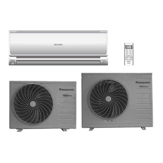
Indoor Unit
CS-LE9NKD
CS-LE12NKD
WARNING
10.1 Select the Best Location ..............................16
10.2 Indoor Unit....................................................17
10.3 Outdoor Unit .................................................19
11. Service Mode ....................................................22
11.1 Auto OFF/ON Button....................................22
12. Operation Control.............................................25
12.1 Basic Function..............................................25
12.2 Indoor Fan Motor Operation.........................27
12.3 Outdoor Fan Motor Operation ......................28
13. Protection control ............................................31
13.1 Protection Control for All Operations ...........31
Operation...............................................................33
(Heating)................................................................34
14. Troubleshooting Guide....................................36
14.1 Refrigeration cycle system ...........................36
© Panasonic Appliances Air-Conditioning (Guangzhou)
Co.,Ltd (PAPAGZ )2012. Unauthorized copying and
distribution is a violation of law.
Order No: PAPAGZ120408CE
Outdoor Unit
CU-LE9NKD
CU-LE12NKD
Advertisement
Table of Contents

Related Manuals for Panasonic CS-LE9NKD


Summary of Contents for Panasonic CS-LE9NKD
-
Page 1: Table Of Contents
13.3 Indoor Piping Air Temperature Control 9. Printed Circuit Board ........15 (Heating)..............34 Indoor Unit............15 14. Troubleshooting Guide........36 10. Installation Instruction........16 14.1 Refrigeration cycle system ......36 © Panasonic Appliances Air-Conditioning (Guangzhou) Co.,Ltd (PAPAGZ )2012. Unauthorized copying and distribution is a violation of law. - Page 2 14.2 Breakdown Self Diagnosis Function ....37 15. Technical Data ..........39 15.1 Operation Characteristics......39 16. Disassembly and Assembly Instructions ..47 17. Exploded View and Replacement Pars List ...51 17.1 Indoor Unit ............51 17.2 Outdoor Unit ..........53...
-
Page 3: Safety Precautions
1. Safety Precautions • Read the following “SAFETY PRECAUTIONS” carefully before perform any servicing. • Electrical work must be installed or serviced by a licensed electrician. Be sure to use the correct rating of the power plug and main circuit for the model installed. •... - Page 4 17. During installation, install the refrigerant piping properly before running the compressor. Operation of compressor without fixing refrigeration piping and valves at opened condition will cause suck-in of air, abnormal high pressure in refrigeration cycle and result in explosion, injury etc. 18.
-
Page 5: Specification
2. Specification Indoor CS-LE9NKD CS-LE12NKD Model Outdoor CU-LE9NKD CU-LE12NKD Phase, Hz Single, 50 Single, 50 Power Supply Rate Rate 0.90 2.50 3.00 0.900 3.300 3.900 Capacity BTU/h 3070 8530 10230 3070 11250 13300 kcal/h 2150 2580 2840 3350 Running Current 3.70... - Page 6 /min (ft 12.0 (424) 13.3 (470) Q-Lo /min (ft 6.8 (239) 8.0 (283) Indoor Airflow /min (ft 7.9 (279) 9.7 (344) (HEATING) /min (ft 9.2 (326) 11.1 (392) /min (ft 11.5 (406) 12.6 (445) Hi (Cooling) /min (ft 32.9 (1162) 36.8 (1300) Outdoor Airflow Hi (Heating)
-
Page 7: Features
3. Features • Inverter Technology Wider output power range Energy saving Quick Cooling More precise temperature control • Long Installation Piping CS/CU-LE9/12NKD, long piping up to 15 meters. • Easy to use remote control • Quality Improvement Random auto restart after power failure for safety restart operation Gas leakage protection Prevent compressor reverse cycle Inner protector to protect compressor... -
Page 8: Location Of Controls And Components
4. Location of Controls and Components Indoor Unit Front Panel Human activity Receiver sensor INDICATOR POWER GREEN Horizontal airflow Vertical airflow TIMER ORANGE Air Filter Direction louver Direction louver AUTO COMFORT GREEN ECONAVI GREEN Outdoor Unit Remote Control Transmitter Operation mode OFF/ON Temperature setting Fan speed selection... -
Page 9: Dimensions
5. Dimensions Indoor Unit Unit: : : : mm... -
Page 10: Outdoor Unit
Outdoor Unit CU-LE9NKD Unit: mm CU-LE12NKD... -
Page 11: Refrigeration Cycle Diagram
6. Refrigeration Cycle Diagram CS/CU-LE9NKD, CS/CU- LE12NKD COOLING HEATING... -
Page 12: Block Diagram
7. Block Diagram... -
Page 13: Block Diagram
8. Block Diagram CS/CU-LE9NKD... - Page 14 CS/CU-LE12NKD...
-
Page 15: Printed Circuit Board
9. Printed Circuit Board Indoor Unit... -
Page 16: Installation Instruction
10. Installation Instruction 10.1 Select the Best Location 10.1.3 Indoor/Outdoor Unit Installation 10.1.1 Indoor Unit Diagram • Do not install the unit in excessive oil fume area such as kitchen, workshop and etc. • There should not be any heat source or steam near the unit. •... -
Page 17: Indoor Unit
10.2 Indoor Unit 10.2.1 How to Fix Installation Plate The mounting wall is strong and solid enough to prevent it from the vibration. The centre of installation plate should be at more than 450 mm at right and left of the wall. The distance from installation plate edge to ceiling should more than 120mm. - Page 18 10.2.3 Indoor Unit Installation...
-
Page 19: Outdoor Unit
10.2.4 Connect the Cable to the Indoor Unit The inside and outside connecting cable can be connected without removing the front grille. Connecting cable between indoor unit and outdoor unit shall be approved polychloroprene sheathed 4x 1.5mm flexible cords, type designation 245 IEC 57 or heavier cord. Ensure the color of wires of outdoor unit and the terminal numbers are the same to the indoor’s respectively. -
Page 20: Evacuation Of The Equipment
Caution : Do not over tighten. Over tightening causes gas leakage Piping size Torque 1/4” 18 N• m (1.8kgf•m) 3/8” 42 N• m (4.2kgf•m) 1/2” 55 N• m (5.5kgf•m) Connecting the piping to outdoor unit Decide piping length and then cut by using pipe cutter. Remove burrs from cut edge. Make flare after inserting the flare nut (locate at valve) onto the copper pipe. -
Page 21: Connect The Cable To The Outdoor Unit
CAUTION: ● If gauge needle does not move from 0 cmHg (0 Mpa) to -76 cmHg (-0.1 Mpa), in step 3 above take the following measure: ● If the leak stops when the piping connections are tightened further, continue working from step 3. ●... -
Page 22: Service Mode
11. Service Mode 11.1 Auto OFF/ON Button Auto OFF/ON Button 1. AUTO OPERATION MODE Once the Auto OFF/ON button is slightly pressed, the unit will immediately operate in Auto operation. This operation can be used to operate air conditioner with limited function if remote control is misplaced or malfunction. -
Page 23: Operate And Display Of Remote Control
11.3 Operate and Display of Remote Control 11.3.1 Original setting 11.3.2 Mode selecting button UTO, HEAT, COOL, DRY can be selected by pressing “MODE” button. Initial display of LCD is as follow *Keeping the button depressed continuously, the operation mode will change in the following order in turn AUTO—HEAT—COOL—DRY–AUTO 11.3.3 Temperature adjusting button Temperature adjusting range is between 16 ℃~30 ℃... - Page 24 11.3.7 AUTO COMFORT button To maximize comfort. Start AUTO COMFORT operation: Press AUTO COMFORT button on remote control, “ECONAVI” displays on remote control screen and send signal to indoor unit to turn on AUTO COMFORT operation mode. AUTO COMFORT indicator on indoor unit lights up. To stop AUTO COMFORT operation, press AUTO COMFORT button again.
-
Page 25: Operation Control
NOTE: OFF Timer and OFF- ON Timer can only be set during the operation; Timer setting can operate only once. If the OFF/ON button on the remote control or the AUTO Switch on the indoor unit is pressed, the timer setting will be cancelled. - Page 26 12.1.2 Cooling Operation 12.1.2.1 Thermostat control • Compressor is OFF when Intake Air Temperature – Internal Setting Temperature < -1.5℃ • Compressor is ON after waiting for 3 minutes, if the Intake Air Temperature – Internal Setting Temperature > Compressor OFF point +0.5K. 12.1.3 Soft Dry Operation 12.1.3.1 Thermostat control...
-
Page 27: Indoor Fan Motor Operation
12.1.5 Automatic Operation • Once AUTO mode is selected, operation mode is determined by set temperature of remote control and indoor intake temperature. judgment JUDGE CONDITION REFERANCE MODE If indoor intake temp – Remote control Cool mode temp setting ≥ +2 Dry mode If -2 ≤... -
Page 28: Outdoor Fan Motor Operation
Remote control QUIET Model COOLING(rpm) 1060 CS-LE9NKD HEATING(rpm) 1020 COOLING(rpm) 1150 1060 CS-LE12NKD HEATING(rpm) 1100 1030 Auto Fan Speed (Cooling, Soft Dry Mode) According to room temperature and setting temperature, indoor fan speed is determined automatically. The indoor fan will operate according to pattern below. -
Page 29: Powerful Operation
12.3.3 Powerful operation ● To cooling or heating the room faster comparing to normal operation. The POWERFUL operation can be active or stop by pressing POWERFUL button on remote control. ● When powerful operation is active, the unit will continuously operate in POWERFUL mode until cancel the mode by pressing POWERFUL button on remote control. -
Page 30: Indication Panel
(4) Human presence or absence detection flow: Process infrared sensor output signal of Human detection every 3 seconds. Record human detection result save the result once every 30 seconds. Presence / absence detection Compare current and previous human detection result every 30 seconds to determine the presence or absence of human. -
Page 31: Protection Control
Timer Signal Receiving sound During Operation. Timer Signal Receiving Sound When the Air Conditioner Stops. 13. Protection control 13.1 Protection Control for All Operations 13.1.1 Time Delay Safety Control ● The Compressor will not turn on within 3 minutes from the moment operation stops, although the unit is turned on again by pressing OFF/ON button at remote control within this period. - Page 32 ● If the set value is exceeded again within 30 seconds, the operation will restart after one minute. ● If this condition repeats continuously for seven times, all indoor and outdoor relays will be cut off. ● Error code [F99] will be displayed. Overheating protection control When the IPM temperature rises to 120 ℃...
-
Page 33: Protection Control For Cooling And Soft Dry Operation
13.2 Protection Control For Cooling and Soft Dry Operation 13.2.1 Outdoor Air Temperature Control • The compressor operating frequency is regulated in accordance to the outdoor air temperature as shown in the diagram below. • This control will begin 1 minute after the compressor starts. •... -
Page 34: Indoor Piping Air Temperature Control (Heating)
- Outdoor air temperature is less than 34℃. • This control stopped if anyone of the following conditions is achieved: - Outdoor air temperature is over 34℃ - Intake air temperature is less than 24℃. - Operation without Cooling or Soft Dry Mode. 13.2.4 Overload Protection for Cooling Operation Frequency of compressor will change according to the outdoor piping temperature. - Page 35 13.3.2 Overload Protection Control Frequency of compressor is determined by indoor piping temperature.
-
Page 36: Troubleshooting Guide
14. Troubleshooting Guide 14.1 Refrigeration cycle system In order to diagnose malfunctions, make sure that there are no Normal Pressure and Outlet Air Temperature (Standard) Gas Pressure Outlet air electrical problems before inspecting the refrigeration cycle. Such Temperature problems include insufficient insulation, problem with the power (kg/cm (°... -
Page 37: Breakdown Self Diagnosis Function
14.1.2 Relationship between the condition of the air conditioner and pressure and electric current Cooling Mode Heating Mode Condition of the Electric current High High Electric current air conditioner Low Pressure during Low Pressure Pressure Pressure during operation operation Insufficient refrigerant (gas leakage) Clogged capillary... - Page 38 14.2.3 Error Codes Table Emergency Code Abnormality/Protection Judgment Check Operation Normal Indoor/Outdoor abnormal >1 minute after starting Connecting cable, ○ communication operation Indoor/outdoor PCB Intake air temperature Indoor intake air temp sensor sensor(defected or × abnormality disconnected) Compressor tempeature Outdoor compressor Continue for 5 sec.
-
Page 39: Technical Data
15. Technical Data 15.1 Operation Characteristics 15.1.1 CS-LE9NKD CU-LE9NKD Cooling Characteristic at Different Outdoor Air Temperature... - Page 40 Cooling Characteristic at Different Piping Length...
- Page 41 Heating Characteristic at Different Outdoor Air Temperature...
- Page 42 Heating Characteristic at Different Piping Length...
- Page 43 15.1.2 CS-LE12NKD CU-LE12NKD Cooling Characteristic at Different Outdoor Air Temperature...
- Page 44 Cooling Characteristic at Different Piping Length...
- Page 45 Heating Characteristic at Different Outdoor Air Temperature...
- Page 46 Heating Characteristic at Different Piping Length...
-
Page 47: Disassembly And Assembly Instructions
16. Disassembly and Assembly Instructions WARNING High Voltage is generated in the electrical parts area by the capacitor. Ensure that the capacitor has discharged sufficiently before proceeding with repair work. Failure to heed this caution may result in electric shocks. Removal Procedure for front panel 1. - Page 48 2.Remove the air filters and then pull out the front grille form the unit body. Front grille Removal Procedure for Discharge Grille 1. Separate the drain hose and the drain plate. 2. Loose fixing screw to remove the Human sensor 3.
- Page 49 Removal Procedure for Main Electronic Controller 1. Remove top cover of C-box and PCB holder Control board cover Holder Main PCB Indicator & receiver 2. Slightly pull out the supporting hook to the right side and pull up a bit the main PCB. Then release the lead wire connected to CN-FM, CN-FB, CN-STM3, CN-HUMAN, CN-TH, AC2, AC4 on main PCB, disconnect the wire connected to terminal 1(L), 3.
- Page 50 3.After removing the bearing, indoor fan can be taken out from the left side Bearing 4.Lift up the indoor fan slightly, and then pull the fan motor out. Fan motor Removal Procedure for Human activity sensor complete Loose the screw of human sensor complete, which is fixing to the discharge grille. Remove the upper cover of human sensor complete, take out the sensor PCB, disconnect the wire connector to CN2 of sensor PCB.
-
Page 51: Exploded View And Replacement Pars List
17. Exploded View and Replacement Pars List 17.1 Indoor Unit CS-LE9NKD, CS-LE12NKD... - Page 52 Parts Name Q’ty CS-LE9NKD CS-LE12NKD REMARK CHASSIS COMPLETE CWD50C1728 CWD50C1728 FAN MOTOR(AC,220V,25W) CWA921477 CWA921475 CROSS FLOW FAN COMPLETE CWH02C1101 CWH02C1101 EVAPORATOR CWB30C3955 CWB30C3955 AUXILIARY TUBE ASS’Y CWT01C5374 CWT01C5374 DRAIN PLUG CWH521096 CWH521096 DISCHARGE GRILLE COMPLETE CWE20C3303 CWE20C3303 AIR SWING MOTOR(DC,12V,200 )
-
Page 53: Outdoor Unit
17.2 Outdoor Unit CU-LE9NKD... - Page 54 CU-LE12NKD...
- Page 55 PART NAME&DESCRIPTION Q'TY CU-LE9NKD CU-LE12NKD REMARK CHASSIS ASS'Y CWD52K1299A CWD52K1284A FAN MOTOR BRACKET CWD541177 CWD541145 SCREW-FAN MOTOR BRACKET CWH551148A CWH551148A FAN MOTOR(AC,220V,20W) CWA951835 FAN MOTOR(AC,220V,30W) CWA951787 SCREW-FAN MOTOR MOUNT CWH551148A CWH551148A PROPELLER FAN ASS'Y CWH03K1069 CWH03K1069 NUT-PROPELLER FAN CWH561036J CWH561036J COMPRESSOR CWB092606 CWB092605...