Advertisement
Quick Links
Advertisement

Related Manuals for Boomerang XL


Summary of Contents for Boomerang XL
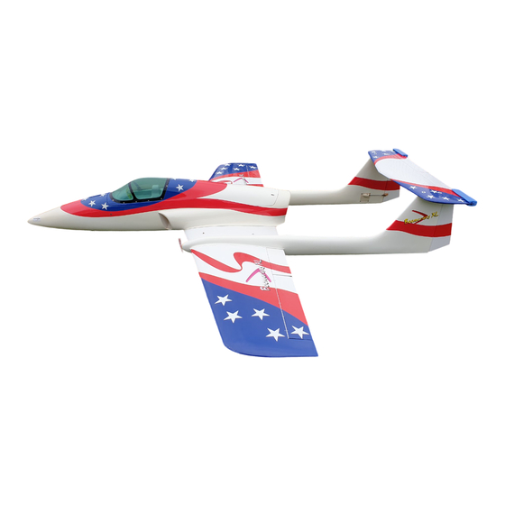
- Page 1 Boomerang RC Jets, LLC. Website www.Boomerang-RC-Jets.com Boomerang RC Jets, LLC.
- Page 2 1 set heavy duty retracts, (Boomerang Jets option available) 1 set of wheels and brakes, (Boomerang Jets option available) 1 set wire legs, (5/6mm) or oleos (Boomerang Jets option available) 1 X electronic air valve for retracts, 1 X electronic air valve for brakes, 8 servos for control surfaces (5 to 8K torque digitals suggested) 1 servo for nose leg steering.
- Page 3 Centre Wing Topside Iron the area lightly through a cloth with a warm iron before cutting away the covering film from the exit holes. Self-adhesive Wing Top Self-adhesive Cut away covering film. Self-adhesive Be sure to glue securely. Warning! This is Vital for safe flying! Centre Wing Underside Iron the main landing gear area lightly through a cloth with a warm iron before cutting away the covering film.
- Page 4 Requires some modification Main Retracts on main gear cover. 2.6 x12mm TP Screw Not Supplied. Not Supplied. 2.6 x12mm Not Supplied. TP Screw Not Supplied. 2.6 x12mm TP Screw Pass all 8 servo wires and air lines through the Cut off shaded portion. centre wing before you trim the whe el wells to Wheel Wells...
- Page 5 Servo Mounts Assemble left and right sides the same wa.y Position of holes may need adjustment depending on servo brand used Wings Lightly iron the covering film through a cloth and cut away allowing 3 mm overhang all round. The servo mounts will hold the cut edges down when they are fixed in place. Assemble left and right sides the same wa Be sure to apply instant type CA glue to...
- Page 6 Servo Mounts Fix servos using servo mounts supplied. 2.6 x12mm TP Screw Not Supplied. Not Supplied. Not Supplied. 2.6 x 12mm TP Screw Servo Mounts Note: - Both flap servos are the same hand to ensure identical movement. Allow 120 mm (5”) overhang of servo leads. 2.6 x12mm TP Screw Extension lead 300 mm from ailerons in outer wings...
- Page 7 Alloy dowels 9x285mm 9x285mm Screw in the 9 X 285 mm alloy dowels. Ensure at least 120 mm (5”) servo wire minimum overhang (to pass through the booms when field assembling) Rudder Servo Extension lead 1 metre along booms to rudders 2.6 x12mm TP Screw 2.6 x12mm TP Screw...
- Page 8 Rudders Assemble left and right sides the same way. Use thin cyano both sides of each hinge not supplied 3mm. or 4/40 pushrod and clevises (not supplied). not supplied Assemble left and right sides the same way. Lightly iron covering through a cloth with warm iron before cutting away covering film, Tailplane/Stab (leaving 3 mm.
- Page 9 Not Supplied Right boom shown. scorch the Heat Gun Be carefl u l not to heat-shr1n · k Tube 2m x 40mm Heat-shrink Tube...
-
Page 10: Tail Assembly
Wing Locking Lock Wing Top 2.5mm Hex Wrench 3x6mm Bolt 3x6mm Bolt 3 x 6mm Bolt Self adhesive Tail Assembly 3 x 30mm Bolt 3 x 30mm Bolt Decrease size of top exit hole after wires are through to prevent the connector falling inside the fin. - Page 11 Additional safety fitting to stabilisor With tailplane (Stab.) firmly screwed down, pass a 3.6mm drill through the holes in the fins and drill a hole through the metal tongue projecting down from the Stab. Remove the Stab and tap the new hole in the tongue out to 4mm thread.
- Page 12 Gluing fuselage to wing...
- Page 13 Check belly pan for fit, mark, then lightly iron covering, then cut away wing covering as you did with the fuselage, to expose Balsa. Glue i n place." Fuel Tank etc Suggested Fuel Tank 3 li t re pop bottle The tank mounting formers can be cut away to accommodate a larger tank if required.
- Page 14 "Trim hatch latch and if necessary adjust the 6mm. dowels to achieve a good fit." 4mm Blind Nut ---------------------------- 1 4mm Washer -- ---- - ----------------------· 1 Set the travel the values show below lf necessary, the use of l a rge nicad packs will give the correct for the first flights.
- Page 15 You will find that there is almost no trim change when using the flaps. The original XL models all used crow braking. If you have a suitable computer transmitter, have the ailerons on two separate channels and the flaps on a single channel using a Y lead.
-
Page 16: Important Warning
Further, Boomerang RC Jets, LLC. reserves the right to change or modify this warranty without notice. In that Boomerang RC Jets, LLC. has no control over the assembly or materials used by the builder of the model during final assembly, no liability shall be assumed nor accepted for any damage resulting from the use of the final user-assembled product.
Need help?
Do you have a question about the XL and is the answer not in the manual?
Questions and answers