Table of Contents
Advertisement
Quick Links
Download this manual
See also:
User Manual
Advertisement
Table of Contents
Troubleshooting

Related Manuals for Motorola V80


Summary of Contents for Motorola V80
- Page 1 Level 1 and 2 Service Manual Tri-Band Digital Wireless Telephone GSM 900/1800/1900 MHz GPRS...
-
Page 3: Table Of Contents
1 and 2 Contents Level 1 and 2 Service Manual Contents 6809471A72-O Contents Contents ..................3 Introduction . - Page 4 Contents April 14, 2004 6809471A72-O...
-
Page 5: Introduction
Available on a contract basis, Motorola Inc. offers comprehensive maintenance and installation programs which enable customers to meet requirements for reliable, continuous communications. To learn more about the wide range of Motorola service programs, contact your local Motorola products representative or the nearest Customer Service Manager. Product Identification Motorola products are identified by the model number on a label usually located under the battery. -
Page 6: Computer Program Copyrights
The Motorola products described in this manual may include Motorola computer programs stored in semiconductor memories or other media that are copyrighted with all rights reserved worldwide to Motorola. Laws in the United States and other countries preserve for Motorola, Inc. certain exclusive rights to the copyrighted... -
Page 7: Warranty Service Policy
Customer’s original phones will be repaired but not refurbished as standard. Appointed Motorola Service Hubs will perform warranty and non-warranty field service for level 2 (assemblies) and level 3 (limited PCB component). Motorola High Tech Centers will perform level 4 (full component) repairs. -
Page 8: Parts Replacement
When ordering replacement parts or equipment, include the Motorola part number and description used in the service manual. When the Motorola part number of a component is not known, use the product model number or other related major assembly along with a description of the related major assembly and of the component in question. -
Page 9: Specifications
Level 1 and 2 Service Manual Specifications Specifications General Function Specification 880-915 MHz Tx (with EGSM) Frequency Range GSM 900 925-960 MHZ Rx Frequency Range DCS 1800 1710-1785 MHz Tx 1805-1880 MHz Rx Frequency Range PCS 1900 1850-1910 MHz Tx 1930-1990 MHz Rx Channel Spacing 200 kHz... - Page 10 Specifications Speech Coding Function Specification Bit Rate 13.0 kbps (FR) 12.2 kbps (EFR) 4.75 - 12.2 kbps (8 AMR TCH/FS modes) 5.6 kbps (HR) 4.75 - 7.95 kbps (6 AMR TCH/HS modes) Frame Duration 4.615 ms Block Length 260 bits Classes Class 1A = 50 bits;...
-
Page 11: Product Overview
Message Service (SMS) text messaging, Enhanced Message service (EMS), Multimedia Messaging Service (MMS), and includes personal information manager (PIM) functionality. The V80 is a tri-band phone that allows roaming within the GSM 900 MHz, digital cellular system (DCS) 1800 MHz, and personal communication service (PCS) 1900 MHz bands. - Page 12 Product Overview cell broadcast messages • Supports GPRS, circuit switched, and SMS networks • Email: POP3 and IMAP4 • WAP 2.0 compliant • Supports SIM Toolkit (STK), Class 2 • Caller ID with link to phone book alerts • Dual thin film technology (TFT) displays with electroluminescent (EL) backlighting: internal 176 X 220 pixel resolution.
- Page 13 Level 1 and 2 Service Manual Product Overview V80 telephones also include a voice note recorder that allows up to 2 minutes of personal messages to be recorded. This feature has a complete set of record, playback, and management tools that make it easy to store and maintain a list of personal memos.
- Page 14 Product Overview Other Features Detailed descriptions of these and the other V80 features can be found in the appropriate V80 telephone user guide listed in the “Related Publications” section toward the end of this manual. April 14, 2004 6809471A72-O...
-
Page 15: General Operation
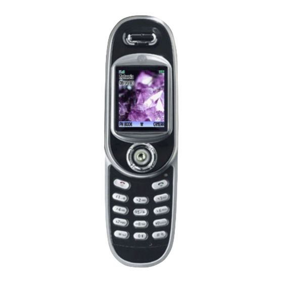
General Operation Controls, Indicators, and Input/Output (I/O) Connections The V80 telephone’s controls are located on the sides of the device and on the keypad (see Figure 1). Indicators, in the form of icons, are displayed on the LCD V80 phones have an audible alert transducer on the top and I/O connectors, consisting of a headset jack and an accessory port, located on the top and bottom of the phone. - Page 16 General Operation Display animation makes the phone’s menus move smoothly as the user scrolls up and down. Turn animation off to conserve the battery. — Service Provider Date Messages 10/15/03 Browser Recent Calls à Clock Phonebook STYLES CAMERA Left Soft Key Right Soft Key Label Label...
-
Page 17: User Interface Menu Structure
Figure 3. Telephone Menu Structure Alert Settings V80 telephones include up to 32 preset alert tones and vibrations that can be applied to all alert events at the same time. ➧ Pressing either volume key mutes the alert. -
Page 18: Operation
General Operation Battery Removal Removing the battery causes the device to immediately shut down and any pending work (for example, partially entered phone book entries or outgoing messages) is lost. ➧ To ensure proper memory retention, turn OFF the phone before removing the battery. -
Page 19: Tools And Test Equipment
Used to enable manual test mode 1. To order in North America, contact Motorola Aftermarket and Accessories Division (AAD) at (800) 422-4210 or FAX (800) 622-6210; Internationally, AAD can be reached by calling (847) 538-8023 or by fax (847) 576-3023. -
Page 20: Disassembly
Disassembly Disassembly The procedures in this section provide instructions for the disassembly of a V80 telephone. Tools and equipment used for the phone are listed in Table 1, preceding. Many of the integrated devices used in this phone are vulnerable to damage from electrostatic discharge (ESD). -
Page 21: Removing And Replacing The Battery
Level 1 and 2 Service Manual Disassembly Removing and replacing the Battery Remove the battery cover as described in the procedures. Lift the end of the battery and remove it completely (See Figure 5). 020201o Figure 5. Removing the Battery There is a danger of explosion if the Lithium Ion battery is replaced incorrectly. -
Page 22: Removing And Replacing The Subscriber Identity Module (Sim)
Disassembly Removing and Replacing the Subscriber Identity Module (SIM) Remove the battery housing and battery as described in the procedures. Slide the SIM latch away from the SIM card to unlock as shown in Figure 6. Carefully lift the SIM from its holder. SIM Latch 040151o Figure 6. -
Page 23: Removing And Replacing The Antenna Housing
Level 1 and 2 Service Manual Disassembly Removing and Replacing the Antenna Housing Remove the battery cover, battery, and SIM as described in the procedures. Use the disassembly tool to release the antenna housing latches at the sides of the antenna housing. Lift the bottom end of the antenna housing off the phone followed by the top end (See Figure 7). -
Page 24: Removing And Replacing The Rear Housing Assembly
Disassembly Removing and Replacing the Rear Housing Assembly This product contains static-sensitive devices. Use anti-static handling procedures to prevent electrostatic discharge (ESD) and component damage. Remove the battery cover, battery, SIM, and antenna housing as described in the procedures. Using a Torx driver with a T-6 bit, remove the 4 screws from the rear housing assembly (See Figure 8). -
Page 25: Removing And Replacing The Camera Assembly
Level 1 and 2 Service Manual Disassembly Removing and Replacing the Camera Assembly Remove the battery cover, battery, SIM, antenna housing, rear housing assem- bly as described in the procedures. Use the disassembly tool to unseat the camera assembly connector from its socket connector. -
Page 26: Removing And Replacing The Transceiver Board Assembly
Disassembly Removing and Replacing the Transceiver Board Assembly This product contains static-sensitive devices. Use anti-static handling procedures to prevent electrostatic discharge (ESD) and component damage. Remove the battery cover, battery, SIM, antenna housing, rear housing assem- bly, and camera assembly as described in the procedures The flexible printed cable (FPC) (flex) is easily damaged. - Page 27 Level 1 and 2 Service Manual Disassembly Gently lift the transceiver board and carefully pass the flex connector through the opening in the transceiver board (See Figure 11). Tramsceiver PC Board Display Flex Connector 040175o Figure 11. Removing the Transceiver Board After the flex connector is clear of the transceiver board, lift the transceiver board assembly from the phone.
-
Page 28: Removing And Replacing The Keypad
Disassembly Removing and Replacing the Keypad Remove the battery cover, battery, SIM, antenna, rear housing assembly, and transceiver board assembly as described in the procedures. Use the plastic tweezers to lift the keypad from the front housing as shown in Figure 12. -
Page 29: Removing And Replacing The Microphone
Level 1 and 2 Service Manual Disassembly Removing and Replacing the Microphone Remove the battery cover, battery, SIM, antenna, rear housing assembly, and transceiver board assembly as described in the procedures. Using the tweezers, carefully lift the microphone out of the transceiver board assembly (See Figure 13). -
Page 30: Removing And Replacing The Real-Time Clock (Rtc) Battery
Disassembly Removing and Replacing the Real-Time Clock (RTC) Battery Remove the battery cover, battery, SIM, antenna housing, rear housing assem- bly, and transceiver board assembly as described in the procedures. Note battery polarity (positive terminal facing upward) before removing the RTC battery. -
Page 31: Removing And Replacing The Blade Assembly
Level 1 and 2 Service Manual Disassembly Removing and Replacing the Blade Assembly Remove the battery cover, battery, SIM, antenna housing, rear housing assembly, transceiver board assembly, and keypad as described in the procedures. Using a T3 driver, remove the 4 screws on the back of the blade assembly. Set the screws aside for reuse (See Figure 15). -
Page 32: Removing And Replacing The Display Module
Disassembly Removing and Replacing the Display Module The flexible printed cable (FPC) (flex) is easily damaged. Exercise extreme care when handling. Remove the battery cover, battery, SIM, antenna housing, rear housing assembly, transceiver board assembly, keypad and blade assembly as described in the procedures. -
Page 33: Subscriber Identity Module (Sim) And Identification
The Mechanical Serial Number (MSN) is an individual unit identity number and remains with the unit throughout the life of the unit. The MSN can be used to log and track a unit on Motorola's Service Center Database. The MSN is divided into 4 sections as shown in Figure 17. - Page 34 Subscriber Identity Module (SIM) and Identification International Mobile Station Equipment Identity (IMEI) The International Mobile station Equipment Identity (IMEI) number is an individual number unique to the PCB and is stored within the unit's memory. The IMEI uniquely identifies an individual mobile station and thereby provides a means for controlling access to GSM networks based on mobile station types or individual units.
-
Page 35: Troubleshooting
Troubleshooting Troubleshooting Manual Test Mode Motorola V80 telephones are equipped with a manual test mode capability. This allows service personnel to verify functionality and perform fault isolation by entering keypad commands. To enter the manual test command mode, a GSM/DCS test SIM must be used. - Page 36 Troubleshooting Table 3. Manual Test Commands (Continued) Key Sequence Test Function/Name Remarks 5*0*8 Set audio level 8 5*0*9 Set audio level 9 5*0*10 Set audio level 10 5*0*11 Set audio level 11 5*0*12 Set audio level 12 5*0*13 Set audio level 13 5*0*14 Set audio level 14 5*0*15...
-
Page 37: Troubleshooting Chart
Level 1 and 2 Service Manual Troubleshooting Troubleshooting Chart Table 4. Level 1 and 2 Troubleshooting Chart Symptom Probable Cause Verification and Remedy 1. Telephone will not turn on or stay on. a) Battery either discharged or Measure battery voltage across a 50 ohm (>1 defective. - Page 38 Troubleshooting Table 4. Level 1 and 2 Troubleshooting Chart (Continued) Symptom Probable Cause Verification and Remedy 5. Telephone transmit audio is weak. a) Microphone connections to the Gain access to the microphone as described in the (usually indicated by called parties transceiver board assembly procedures.
-
Page 39: Programming: Software Upgrade And Flexing
Number Charts The following charts are provided as a reference for the parts associated with V80 telephones. Related Publications Motorola V80 User Guide, English 6809469A53 (SJJN5445) note: kit numbers are not all inclusive and may change without notice. 6809471A72-O... -
Page 40: Exploded View Diagram
Troubleshooting Exploded View Diagram Figure 18. Main Assembly Exploded View April 14, 2004 6809471A72-O... -
Page 41: Exploded View Parts List
Level 1 and 2 Service Manual Troubleshooting Exploded View Parts List Table 5. Main Assembly Exploded View Parts List Item Motorola Part Description Number Number 1586821P01 Battery Door SNN5614 Battery Slim Li Ion 0309315B07 Back Housing Screws 1586818P01 Back Housing... - Page 42 Troubleshooting Figure 19. Blade Assembly Exploded View April 14, 2004 6809471A72-O...
- Page 43 Level 1 and 2 Service Manual Troubleshooting Table 6. V80 Blade Assembly Parts List Item Motorola Part Description Number Number 0170386K01 Blade Lens Assembly, V80 7570382A35 LCD Gasket 3286824P01 Felt, Earpiece, Front 0186857P01 LCD Assembly 3270341C05 Gasket, BTB 3886832P01 Joystick Cluster...
-
Page 44: Accessories
Troubleshooting Accessories Table 7. Accessories Part Description Part Number Mid-Rate travel charger SPN4992 Adapter, travel charger, Euro plug SPN4993 Adapter, travel charger, UK plug SPN4994 Adapter, travel charger, Brazilian plug SPN4741 Adapter, travel charger, Argentinian plug SPN4739 Adapter, travel charger, Korean plug SPN4774 Adapter, travel charger, Hong Kong plug SPN4756... - Page 45 1 and 2 Index Level 1 and 2 Service Manual Index 6809471A72-O identification 33 international mobile station equipment identity 34 alert settings 17 mechanical serial number 33 antenna, removing and replacing 23 product 5 idle display, defined 16 IMEI 34 battery Introduction 5 function 17...
- Page 46 Index removing customer 7 antenna 23 product 7 battery 18, 20 battery cover 20 blade assembly 31 text entry 13 camera assembly 25 tools and test equipment 19 display module 32 transceiver board assembly, removing and replacing 26 keypad 28 troubleshooting 35 microphone 29 manual test mode 35...
- Page 48 MOTOROLA, the Stylized M Logo, and all other trademarks indicated as such herein are trademarks of Motorola, Inc. ® Reg. U.S. Pat. & Tm. Off. TrueSync and Starfish are registered trademarks of Starfish, Inc., a wholly owned independent subsidiary of Motorola, Inc.
Need help?
Do you have a question about the V80 and is the answer not in the manual?
Questions and answers