
Related Manuals for LG CT-20T25M


Summary of Contents for LG CT-20T25M
-
Page 1: Service Manual
COLOR TV SERVICE MANUAL CHASSIS : MC-049B MODEL: CT-20T25M CAUTION BEFORE SERVICING THE CHASSIS, READ THE SAFETY PRECAUTIONS IN THIS MANUAL. -
Page 2: Table Of Contents
CONTENTS Contents ........................2 Safety Precautions....................3 Control Descriptions..................4 Specifications......................7 Adjustment Instructions .................8 T rouble Shooting....................12 Printed circuit board..................16 Block Diagram ......................18 Exploded View....................20 Exploded View Parts List ................21 Replacement Parts List .................22 SVC. Sheet........................- 2 -... -
Page 3: Safety Precautions
SAFETY PRECAUTIONS IMPORT ANT SAFETY NOTICE Many electrical and mechanical parts in this chassis have special safety-related characteristics. These parts are identified by the Schematic Diagram and Replacement Parts List. It is essential that these special safety parts should be replaced with the same components as recommended in this manual to prevent X-RADIATION, Shock, Fire, or other Hazards. -
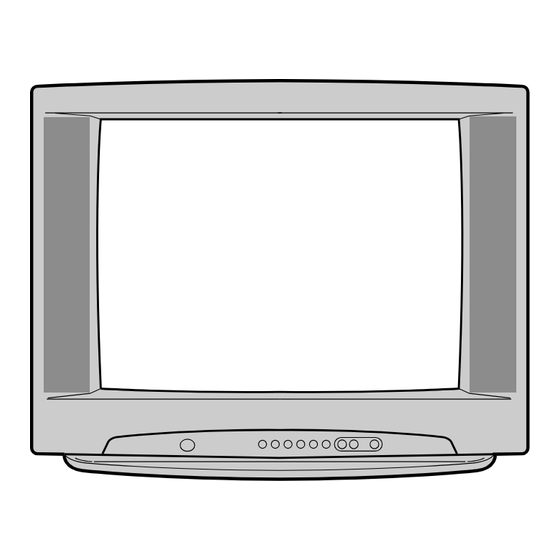
Page 4: Control Descriptions
DESCRIPTION OF CONTROLS All the functions can be controlled with the remote control handset. Some functions can also be adjusted with the buttons on the front panel of the set. Remote control handset Before you use the remote control handset, please install the bat- teries. - Page 5 17. SURROUND (º º / MENU/INDEX TV/AV selects surround sound. 18. VCR BUTTONS control a LG video cassette recorder. 19. PIP BUTTONS (option) switches the sub picture on or off. PR +/- selects a programme for the sub picture. SWAP alternates between main and sub picture.
-
Page 6: Front Panel
Front panel Shown is a simplified representation of front or side panel. Here shown may be somewhat different from your set. VIDEO VIDEO ON/OFF MENU OK VIDEO (L/MONO)-AUDIO-(R) P-TURBO-S (L/MONO) AUDIO AUDIO 2 3 4 ON/OFF MENU OK VIDEO (L/MONO)-AUDIO-(R) S-TURBO-P VIDEO VIDEO... -
Page 7: Specifications
(But, CST must be tested 40 ± 5°C . Humidity : 50%) 2) Relative Humidity : 65 ± 10% 1) Capacity : Follow LG electronics TV testing Standard. 2) Another Required Standard 3) Power : Standard input Voltage (110~240V, 50/60Hz) -
Page 8: Adjustment Instructions
ADJUSTMENT INSTRUCTIONS 1. Application Object 4. Purity & Convergence adjustment These instructions are applied to all of the color TV, MC-049B. As preparatory operations before CPT Assembling assembling CPT, wind cotton Tape for 2. Notes protecting to CPT NECK and DY, CPT connection parts. -
Page 9: Screen Voltage Adjustment
(4) Maintain as angle of (3) and rotate the tab to accord with 2. White balance IIC Parameter vertical line of Red and Blue color in the middle of screen. Program TWBeng_v049 Program TWBeng_v049 Speed Delay (5) Open angle of the two tab of 6 pole magnet by isogonic Vcd Slave BCF0 Eprom_Slave... - Page 10 (4) VS (Vertical Shift) adjustment: 8-4. OPTION2 Function Adjust so that the geometric vertical center line is in accord Option Code Function with vertical center line of CPT. (5) HS(Horizontal Shift) adjustment: Without A/V2 Adjust so that the geometric horizontal center line is in With AV2 accord with horizontal center line of CPT.
- Page 11 8-6. OPTION4 Function Option Code Function ENG ONLY OSD L EU-5EA EU ETC GREECE EU-ALL FARSI ARAB URDU E+HINDI E+I+M+V E+THAI E+CHINA WEST EU TXT L EAST EU1 TURKEY EU EAST EU2 CYRILLIC1 CYRILLIC2 CYRILLIC3 TURK GRE1 TURK GRE2 TURK GRE3 ARAB FRA ARAB ENG ARAB HEB1...
-
Page 12: Trouble Shooting
TROUBLE SHOOTING RF- STEREO MODEL PICTURE O. K / NO SOUND Selec t ed c o rrec t syst em In m enu Chec k t he wavef o rm Chec k / Rep lac e IF 1 o f TU101 TU 101 Chec k t he wavef o rm Chec k The Vo lt ag e... - Page 13 No Ras ter ( 2/ 2) CHECK B+ At D829 c at ho d e No rm al Ab no rm al Op en Is t he vo lt ag e a t Chec k eac h p in vo lag e o f IC11 Fuse o f AC line Chec k / Rep lac e Chec k t he...
- Page 14 NO Pic t ure No So und Is Any OSD d isp la yed ? Chec k IC11 p in71, 7 2, 73 Chec k rec eiving syst em in MENU & exec ut e Aut o Pro g ram . ( R, G, B o ut ) Do es t he auto Pro g ra m Op erat e p ro p erly...
- Page 15 AV STERRO / MONO MODEL Selec t c o rrec t syst em In m enu Chec k t he c o nnec t io n Of AV eq uip m ent Chec k t he wavef o rm At p in16, 17 o f IC11 Chec k TU1 01 Tuner Chec k t he vo lt ag e Chec k t he wavef o rm...
-
Page 16: Printed Circuit Board
PRINTED CIRCUIT BOARD MAIN - 16 -... - Page 17 COMPONENT LOCATION GUIDE R31 ..C3 R506..B3 R810..F3 C10 ..C4 C450..E5 C621..A3 D815 ..G2 G48 ..G3 J217 ..B5 P105A ..A5 P105B ..C5 R32 ..D1 R507..B4 R811..E3 C11 ..C4 C457 ..D5 C622..A3 D821..E2 G49 ..G4 J219 ..D4 P10A ..C2 R33 ..C3 R508..B4 R812 ..G3 C12 ..C3 C501..B4...
-
Page 18: Block Diagram
BLOCK DIAGRAM VIDEO/AUDIO RESET DATA/CLOCK ON / OFF Y/Cb/Cr-IN SCART RGB-IN AV-IN TV / MONITOR OUT PIP-VIDEO PIP-RGB - 18 -... - Page 19 MEMO - 19 -...
-
Page 20: Exploded View
EXPLODED VIEW OPTION - 20 -... -
Page 21: Exploded View Parts List
170-A01D LEAD SET, CPT EARTH(19”) 6410VEH001B POWER CORD, 174-009E CHAUS VDE/SEMKO 2410MM 2P LGESY LOCAL 3091V00517C CABINET ASSEMBLY, CT-20T25M(BARE) CKD MONO MC049B . 3091V00517D CABINET ASSEMBLY, CT-20T25M(PH) MONO MC049B SY ASSEMBLE 5020V00070N BUTTON, CONTROL CT-21T25M(CKD) ABS, HF-380 6KEY 117A SPRAY... -
Page 22: Replacement Parts List
REPLACEMENT PARTS LIST For Capacitor & Resistors, the CC, CX, CK, CN : Ceramic RD : Carbon Film charactors at 2nd and 3rd digit CQ : Polyestor RS : Metal Oxide Film in the P/No. means as follows; CE : Electrolytic RN : Metal Film RF : Fusible LOCA. - Page 23 For Capacitor & Resistors, CC, CX, CK, CN : Ceramic RD : Carbon Film the charactors at 2nd and 3rd CQ : Polyestor RS : Metal Oxide Film digit in the P/No. means as CE : Electrolytic RN : Metal Film follows;...
- Page 24 For Capacitor & Resistors, CC, CX, CK, CN : Ceramic RD : Carbon Film the charactors at 2nd and 3rd CQ : Polyestor RS : Metal Oxide Film digit in the P/No. means as CE : Electrolytic RN : Metal Film follows;...
- Page 25 For Capacitor & Resistors, CC, CX, CK, CN : Ceramic RD : Carbon Film the charactors at 2nd and 3rd CQ : Polyestor RS : Metal Oxide Film digit in the P/No. means as CE : Electrolytic RN : Metal Film follows;...
- Page 26 SW801 SDKEA3 ALPS IEC 250V 8A HORIZONTAL 480G ACCESSORIES 3828VA0475F MANUAL,OWNERS NEU LG AR/EN 124E TX 3828VA0475L MANUAL,OWNERS UKR/BZ03 LG RU/EN 124E TX 340M 6710V00124D REMOTE CONTROLLER,MC049B W/O TXT 132-210J ANTENNA,2 POLE 3 SECTION 700MM 750MM 5010V00004B ANTENNA,3SECTION 750MM NTSC W/ADP...
- Page 27 P/NO: 3854VA0162A - S1 2004.6.12...
-
Page 28: Svc. Sheet
SVC. SHEET : 3854V A0162A-S... - Page 29 July, 2004 P/NO : 3828VD0199K Printed in Korea...
Need help?
Do you have a question about the CT-20T25M and is the answer not in the manual?
Questions and answers