Table of Contents
Advertisement
Quick Links
Advertisement
Table of Contents

Related Manuals for Interlogix TVR-1004-250


Summary of Contents for Interlogix TVR-1004-250
- Page 1 TruVision DVR 10 User Manual P/N 1068258 • REV C • ISS 06APR12...
- Page 2 Trademarks and patents Interlogix, TruVision names and logos are trademarks of UTC Fire & Security. Other trade names used in this document may be trademarks or registered trademarks of the manufacturers or vendors of the respective products.
-
Page 3: Table Of Contents
Content Product introduction 1 Chapter 1 Product overview 1 Features 1 Installation 5 Chapter 2 Installation environment 5 Unpacking the TVR 10 and its accessories 6 HDD capacity 6 Back panel overview 7 Connection diagram 8 Operating instructions 9 Chapter 3 Control interfaces 9 Controlling the TVR 10 9 Front panel overview 10... - Page 4 Utilities settings 81 Chapter 6 Modifying the device name 81 Restoring to factory defaults 82 Managing the hard drive 83 Acknowledging an alarm 84 Rebooting the TVR 10 84 Viewing logs 84 Upgrading the firmware 87 Chapter 7 Upgrade methods 87 Upgrading with a USB flash memory 87 Upgrading through the Web browser 88 Setting up the wftp32 FTP server 89...
-
Page 5: Product Introduction
Chapter 1 Product introduction Product overview This is the TruVision DVR 10 User Manual for models: • TVR-1004-250 • TVR-1004-500 • TVR-1004-1T The TruVision DVR 10 (TVR 10) is a network digital video recorder developed for digital surveillance. The TVR 10 uses an embedded microcontroller unit with the Linux operating system, combining the most advanced technology in video and audio encoding/decoding, hard drive recording, and TCP/IP communication. - Page 6 Chapter 1: Product introduction • Multiple area motion detection • Privacy masking • Tampering alarm view • Video signal loss alarm • Changeable OSD position • Both variable and constant bit rate • Dual-stream, and the substream can support CIF/QCIF resolution Storage The TVR 10 supports the following storage features: •...
- Page 7 Chapter 1: Product introduction • ADSL (PPPoE) dialup function • Programming and setup through browser interface • Remote download and playback the recorded files • Remote upgrade of TVR 10 firmware • PTZ control using Web browser • IE for network control •...
-
Page 9: Installation
Chapter 2 Installation Installation environment When installing your product, consider these factors: • Ventilation • Temperature • Moisture • Chassis load Ventilation: Do not block any ventilation openings. Install in accordance with the manufacturer’s instructions. Ensure that the location planned for the installation of the unit is well ventilated. -
Page 10: Unpacking The Tvr 10 And Its Accessories
Storage capacity for the TruVision DVR 10 varies depending on the model. Refer to Table 1 below for more information. Table 1: TruVision DVR 10 model types Model number Description TVR-1004-250 TruVision DVR Model 10, 4 ch, 250 GB TVR-1004-500 TruVision DVR Model 10, 4 ch, 500 GB TVR-1004-1T... -
Page 11: Back Panel Overview
Chapter 2: Installation Back panel overview Figure 1 below shows the back panel controls and connectors on a typical TruVision series network digital video recorder. Details may vary for specific models. Figure 1: Back panel RS-485 T + T- R + R - POWER AOUT +12V... -
Page 12: Connection Diagram
Chapter 2: Installation Connection diagram Use Figure 2 below as a visual guide to connect the various peripherals to the TVR 10. Figure 2: Rear panel connection diagram RS-485 T+ T- R + R - POWER AOUT +12V VOUT ETHERNET ALARM IN 1 2 3 4 G G L i n k/Act... -
Page 13: Operating Instructions
Chapter 3 Operating instructions Control interfaces The TVR 10 has three control interfaces: • Built-in interface • Display interface • Web browser interface Built-in interface. The built-in interface is displayed on the VBA monitor. It consists of a main menu and several dialog screens that let you configure and control the device. -
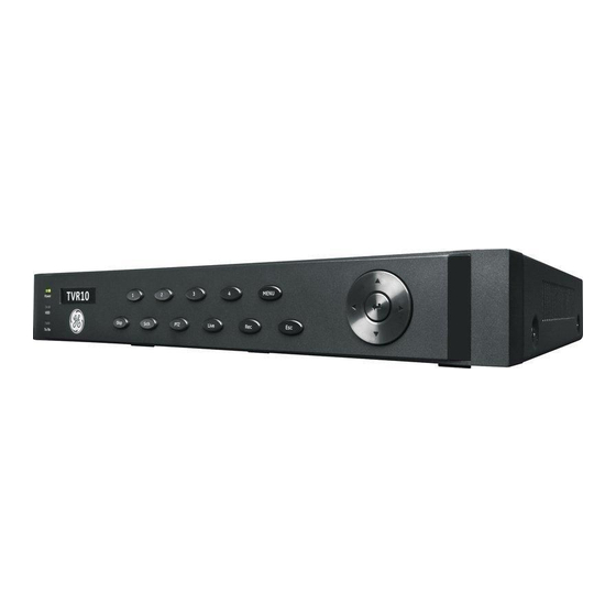
Page 14: Front Panel Overview
Chapter 3: Operating instructions Front panel control. Use the directional arrow buttons to select a command, option, or button on a screen. Use the ENTER button to confirm a selection. IR remote control. Use the directional arrow buttons to select a command, option, or button on a screen. -
Page 15: Using The Mouse
Chapter 3: Operating instructions Item Type Name Description Numeric 1 to 4 Enter numbers from 1 to 4. buttons MENU Switches out of display mode to display the main menu. Function Cancels the current changes and returns to the previous buttons screen or main menu. - Page 16 Chapter 3: Operating instructions Mouse shortcut menu To display the mouse control menu, right-click while in live view. The commands on this shortcut menu are shown in Figure 4 below. Table 3 below describes the commands. Figure 4: Mouse shortcut menu Table 3: Mouse shortcut menu commands Command Description...
-
Page 17: Using The Ir Remote Control
Chapter 3: Operating instructions Using the IR remote control Use the IR remote control to carry out functions similar to the front panel buttons. Figure 5: Controls on the IR remote POWER PQRS WXYZ DE L INFO MENU PLAY VOIP/MON PREV Table 4: IR remote control legend Item... - Page 18 Chapter 3: Operating instructions Item Name Description , , , (arrow In menu mode, the Left or Right Arrow buttons select buttons) commands or options; the Up or Down Arrow buttons edit or select values. OK enters the selection or value. OK (central button) PTZ direction control.
-
Page 19: Using The Web Browser
Chapter 3: Operating instructions • Check the remaining charge in the batteries. • Check that the IR remote control sensor is not masked. If the problem still exists, please contact your administrator. Using the Web browser The TVR 10 Web browser lets you view, record, and play back videos as well as manage all aspects of the TVR 10 from any PC connected to your network. -
Page 20: Playing Back Recorded Video
Chapter 3: Operating instructions Item Name Description Taskbar Displays single or four-screen views. Selects multiscreen. Captures screen. Archives video. Lets you talk through a microphone to a speaker connected to the TVR 10 (bidirectional audio). Video adjust Adjusts video image such as brightness, saturation, hue, and audio volume. -
Page 21: Using The Web Browser To Configure The Device
Chapter 3: Operating instructions To quickly archive a segment of a video you are playing back, click the Save button to begin archiving and click again to stop archiving. The resulting video file is saved on your desktop. Click the Download button to download that video file into your hard drive. Viewing logs To view logs using the Web browser interface, click the Log button on the navigation bar. -
Page 22: Main Menu Overview
Chapter 3: Operating instructions Viewing video in sub-stream To view video in sub-stream, right-click a camera in the Navigator and select Sub-stream. The camera displays video in sub-stream. Main menu overview The built-in interface includes a main menu with eight command buttons. Each command displays a screen that lets you edit a group of TVR 10 settings. -
Page 23: Using The Main Menu
Chapter 3: Operating instructions Table 6: Menu commands and screen options Main menu Dialog screen options Main menu Dialog screen options command command Display Device ID Camera Camera Require password Camera title position Menu timeout Adjust video Video standard Time and date display Enable scaler Motion detection Menu transparency... - Page 24 Chapter 3: Operating instructions Table 7 below shows the front panel buttons you can use to display the main menu or various dialog screens. Table 7: Main menu display Button Action MENU Display the TVR 10 main menu SRCH Display the Play Back screen Display the Manual Record screen Display the PTZ interface Note:...
- Page 25 Chapter 3: Operating instructions Table 8: Types of control on the screen Control Description Provides two values: indicates enabled and × indicates disabled. You can Check box click the check box or use the ENTER or OK button to switch between values. List box Provides more than two values for the option.
-
Page 26: Exiting The Main Menu
Chapter 3: Operating instructions Use the numeric buttons on the remote control to enter characters. Press the numeric buttons repeatedly to cycle through different characters available for that button. The character format and type depends on the value you selected in step 2. -
Page 27: Basic Operation
Chapter 4 Basic operation Turning on the TVR 10 Before turning the TVR 10 power on, make sure that the power supply matches that of the TVR 10 and the AC adapter is connected correctly. Connect at least one monitor to the video out or the VGA interface. Otherwise, you will not be able to see the user interface and operate the device. -
Page 28: Camera Status
Chapter 4: Basic operation Figure 10: Recording status Camera status Each icon represents a camera. The icon color shows the camera status. Table 9 below gives the status color code.. Table 9: Camera status Icon Color Status description White No video signal Yellow Standby recording (when recording upon alarm and/or motion) Green... -
Page 29: Connecting The Spot Monitor
Chapter 4: Basic operation Press DISP to manually toggle through single camera and four-screen views . The single camera display reverts back to camera 1 when switching to single view. You can set the auto live mode on the Display menu. Viewing in multiscreen Mouse Right-click to open the mouse menu, and then click Multi... -
Page 30: Controlling A Ptz Camera
Chapter 4: Basic operation Figure 11: Login screen To log on to the TVR 10 user interface: 1. In the User box, select a user. 2. Enter the corresponding password in the Password edit box. 3. Click Confirm to enter the main menu. If there is no response, it means the user name and password are not matched. -
Page 31: Selecting A Camera
Chapter 4: Basic operation Figure 12: PTZ control interface Selecting a camera When in PTZ control mode, press the numeric buttons to select a camera. For example, press the number 2 button to select the second camera PTZ. After selecting the camera PTZ, you can use the control buttons to control the PTZ. -
Page 32: Manual Recording
Chapter 4: Basic operation Front panel Press PTZ to enter PTZ mode. Press REC and enter a preprogrammed three-digit preset number. Preset starts immediately. If you enter a one or two-digit number, depending on your TVR 10 model, you will change the selected camera. This function is only available if the mouse is not connected to the TVR Remote control Press PTZ to enter PTZ mode. - Page 33 Chapter 4: Basic operation Figure 13: Manual Record screen The controls and options available on the Manual Record screen are described in Table 10 below. Table 11: Manual Record controls and options Option Description Camera Lists the number of cameras the TVR 10 has. Status Camera work status has four values: •...
-
Page 34: Playing Back Video
Chapter 4: Basic operation The Manual Record screen displays listing all cameras. The camera status line shows which cameras are currently recording. 3. Click the camera’s Start/Stop line to begin the recording. A checkmark appears on that camera’s Start/Stop box. 4. -
Page 35: Searching For A Recorded Video
Chapter 4: Basic operation Figure 14: Play Back screen Table 12: Play Back controls and options Option Description Selects a specific camera. Search for Specifies a recorded file type. The file type options include: All, All Time, Motion Detect, Alarm, and Manual. Time Specifies a start and end date/time to conduct a search based on a recording period. -
Page 36: Playing Back A Recorded File
Chapter 4: Basic operation To search for recorded video: 1. Right-click and click Search in live mode or press PLAY on the front panel or the remote control. 2. If requested, enter your user name and password. The Play Back screen displays. -
Page 37: Playing Back Video With A Mouse
Chapter 4: Basic operation Table 13: Playback interface options Option Description MENU Displays or hides the information bar. PLAY Turns the sound on or off. Right or Left Arrow button Adjusts the play progress by percentage (%). Up or Down Arrow button Adjusts the play speed: Normal speed is “1x.”... - Page 38 Chapter 4: Basic operation Figure 15: Playback control interface Table 14: Playback control bar description Control Name Description Skip reverse/forward Skips backward or forward 3% each time. Fast forward/ Slow Adjusts the play speed: Normal speed is “1x.” forward Use the Up Arrow button to increase play speed (2X, 4X).
-
Page 39: Archiving Recorded Files
Chapter 4: Basic operation Archiving recorded files Archive recorded files using an external device. You can also archive specific incidents in a file. You must be in live mode to play back a recorded file. You can insert a mini-USB hub to the USB port to attach a mouse for navigation and a USB drive for archiving. -
Page 40: Archiving A Video Segment
Chapter 4: Basic operation 3. Use the Media box to select the backup device you want to use. 4. Click Archive to start the archiving process. When the archiving starts, a corresponding message box displays, indicating the status. If the selected files exceed the capacity of your storage device, an error message displays. -
Page 41: Turning Off The Tvr 10
Chapter 4: Basic operation Turning off the TVR 10 To turn off the TVR 10: 1. On the main menu, click Utilities, and then click Power Off. — or — Press and hold the Power button on the remote control for at least five seconds. -
Page 43: Advanced Setup
Chapter 5 Advanced setup This chapter covers the advanced setup of your TVR 10. Only users with appropriate access privileges can define and modify advanced configurations. When the following settings are modified and saved, you will be prompted to reboot the TVR 10 in order for the new settings to take effect. You do not need to reboot the device for any other configurations. -
Page 44: Modifying Your Password
Chapter 5: Advanced setup Modifying your password Passwords limit access to the TVR 10 and the same password can be used by several users. When creating a new user, the default password is 0000. Each standard user can modify his or her own password. However, only an administrator can assign or unassign a password to a user. -
Page 45: Adding A New User
Chapter 5: Advanced setup If the initial and verify passwords entered are identical, the password is saved and becomes effective immediately. However, if both passwords do not match, a warning message appears as shown in the figure below. Press ENTER to confirm and you are returned to the password edit box to the new password again. -
Page 46: Assigning Access Privileges
Chapter 5: Advanced setup 4. Click Confirm (or press ENTER) to confirm. The User screen displays with the new user name listed. After adding a new user, the password field remains blank. You can leave the password field blank, or you can assign the user a password. For more information, see “Modifying your password”... -
Page 47: Access Privileges
Chapter 5: Advanced setup Access privileges Access privileges define what areas in the system a user can access. The TVR 10 access privileges are categorized into two different areas: local and remote. Local Local privileges are for local operation, such as the operating the unit using the front panel, IR remote control, and RS-485 interface. -
Page 48: Deleting Users
Chapter 5: Advanced setup Setting up the MAC address Setting up a user with a MAC address from the user’s computer prohibits access to the TVR 10 from other computers. To set up a MAC address: 1. At the PC DOS prompt, use the “ipconfig” command to obtain the MAC address of that PC (in 6 bytes). -
Page 49: Camera Settings
Chapter 5: Advanced setup Camera settings This section describes how to change camera settings from the Camera Configuration screen. Camera options that you can configure are listed below. You can change these settings in any order. The options are: • Name of each camera •... - Page 50 Chapter 5: Advanced setup 2. Select a camera from the Camera box. 3. Enter the new camera name in the Camera Name edit box. Click the Camera Name edit box to enter the edit mode. You can enter numerals, uppercase and lowercase letters (see “Using an edit box” on page 21 for more information).
-
Page 51: Adjusting The Video Image
Chapter 5: Advanced setup • Solid white • Not displayed 3. Enter the Date and Time Position Setup interface. Click the Date & Time OSD Position button to enter the Date and Time Position Setup interface as shown in the figure below. 4. -
Page 52: Privacy Masking
Chapter 5: Advanced setup Figure 17: Adjust video screen To adjust the video image: 1. Display the Camera Configuration screen and select a camera. 2. Click the Adjust Video Setup button to display the Adjust Video screen. 3. Make the appropriate video image adjustments. You can adjust the video image’s brightness, contrast, hue, and saturation by clicking the corresponding Adjust button. - Page 53 Chapter 5: Advanced setup Figure 18: Area masked To define privacy masking: 1. Display the Camera Configuration screen and select a camera. 2. Click Advanced Settings Setup to display the Advanced Settings screen. 3. Select the Enable the Privacy Masking check box to enable privacy masking. 4.
-
Page 54: Camera Tamper Alarm
Chapter 5: Advanced setup 6. Click the mouse to save that area for privacy masking. 7. Press ENTER to return to the Advanced Settings screen. 8. Repeat steps 4 to 7 for additional areas for privacy masking. You can set up four masked areas on a screen. - Page 55 Chapter 5: Advanced setup Figure 19: View Tampering Handle screen Defining a camera tamper alarm requires the following tasks: 1. Specify the detection sensitivity level. 2. Define the on-screen area that can trigger a camera tamper alarm. 3. Configure the tamper alarm response. Note: These tasks define a camera tamper alarm for only a single camera.
-
Page 56: Video Loss Alarm
Chapter 5: Advanced setup To define the tamper alarm response: 1. In the Advanced Settings screen, click Camera Tamper Area to display the Camera Tamper Rules screen. 2. Define an alarm schedule. The system’s handling of a camera tamper alarm depends on the alarm schedule. - Page 57 Chapter 5: Advanced setup Figure 20: Video signal loss handle screen To define a video loss alarm: 1. Display the Camera Configuration screen and select a camera. 2. Click Advanced Settings to display the Advanced Settings screen. 3. Click Video Loss option. The Rules option becomes active. 4.
-
Page 58: Motion Detection Alarm
Chapter 5: Advanced setup 7. Repeat steps 2 to 6 for additional cameras. Motion detection alarm The TVR 10 lets you define motion detection alarms. A motion detection alarm refers to an alarm triggered when a camera detects a motion. The alarm displays on the status bar of the screen. - Page 59 Chapter 5: Advanced setup 4. Define the motion detection area. Move the pointer or use the directional arrow buttons (Up, Down, Left, or Right) to move the yellow pane to the zone you want to mask. Click to select that area for motion detection. The yellow panes turn red, indicating an alarm will trigger if motion is detected within this area.
- Page 60 Chapter 5: Advanced setup 2. Select the cameras you want to record for motion detection. Select the cameras you want to begin recording when the system receives a motion detection alarm. Check one of the camera boxes to select that camera.
-
Page 61: Display Settings
Chapter 5: Advanced setup Check the check box or use the Up or Down Arrow buttons and the ENTER button to enable or disable these options. 5. To copy the alarm rules to another day, select a day in the Copy to list box and click Copy. -
Page 62: Video Output Standard
Chapter 5: Advanced setup To change the device ID: 1. Click Display on the main menu to open the Display screen as shown in the figure below. 2. Click the Device ID edit box to enter into edit mode. 3. Enter the new device ID. The device ID value ranges from 1 to 255. 4. - Page 63 Chapter 5: Advanced setup Figure 21: Date & time screen To configure the TVR 10 system date and time: 1. Select Display in the main menu to display the Display Configuration screen. 2. Click Date & Time Setup to display the Date & Time screen. 3.
-
Page 64: Multi-Screen Layout
Chapter 5: Advanced setup Multi-screen layout When you turn on the TVR 10, the system automatically enters into the live mode. Use the following buttons to toggle between different display options: Button Function DISP Toggles between a single screen display to a four screen display Numeric buttons (1-4) Switch between cameras on a single screen The Multi-Screen screen, displayed in Figure 22 below, lets you configure the... -
Page 65: Recording Settings
Chapter 5: Advanced setup • 1 minute • 2 minutes • 5 minutes • Never Audio preview Check the Audio Preview check box if you want the TVR 10 to play the audio of the camera when displaying a single camera. Display layout setup Use this option to define the order of the cameras to be displayed when in live mode. -
Page 66: Record Mode
Chapter 5: Advanced setup Figure 23: Recording channel configuration Record mode This option lets you specify how the TVR 10 responds when the HDD becomes full. Select Stop Recording to trigger a Hard Disk Full exception. Recording will not continue if the HDD is full and you have the Stop recording option selected. Select Overwrite to overwrite the earliest recorded files when the HDD is full to continue recording. -
Page 67: Defining A Recording Schedule
Chapter 5: Advanced setup Option Description Frame Rate Specifies the frame rate for the selected resolution. Options include: 25 (PAL)/30 (NTSC) 22, 20, 18, 16, 15 , 12, 10, 8, 6, 4, 2, and 1. Pre-Event Time This option is used if you have the motion detection and/or external alarms enabled. - Page 68 Chapter 5: Advanced setup Figure 24: Recording schedule screen To define a recording schedule: 1. Display the Schedule screen. On the Recording Channel Configuration screen, click Record to enable recording. Then click Schedule to display the Schedule screen. 2. Select a day of the week for which you want to set the recording schedule. Select a day of the week using the Day list box to define specific periods for recording during that day.
-
Page 69: Alarm Settings
Chapter 5: Advanced setup Motion or Alarm, or Motion and Alarm in this box. For more information, see “Searching for motion detection video” on page 32. 5. Repeat steps 3 to 4 for additional periods. Note: The four daily time periods cannot overlap. 6. - Page 70 Chapter 5: Advanced setup Figure 25: Alarms screen To set up an external alarm input: 1. Select an alarm input in the Alarm Input box. 2. Select an input type in the Input Type box. Alarm input type refers to the sensor type. You can select Normal Open or Normal Close according to the sensor type.
- Page 71 Chapter 5: Advanced setup Note: In order for a camera to record an alarm, the recording option and type must be enabled on the Schedule screen. See “Defining a recording schedule” on page 63 for more information. 5. Define your alarm handling schedule. In the Alarm Schedule section of the Alarm In Handling screen, define a schedule for when the TVR 10 will respond to an external alarm.
- Page 72 Chapter 5: Advanced setup enter the number for the PTZ preset to be used. See “PTZ settings” on page 74 for more information on defining PTZ presets. Note: Make sure that the PTZ you are using can support preset, preset tour, and shadow tour functions.
- Page 73 Chapter 5: Advanced setup week to which you want to copy this schedule. Select All if the same schedule is used all week. Click Copy. 4. Click Confirm to save your settings and return to the Alarms screen. 5. Copy the alarm output settings to another alarm output if required. To copy the settings to another alarm output, select an alarm output on the Copy to Alarm Out list box then click Copy.
-
Page 74: Network Settings
Chapter 5: Advanced setup Figure 26: Notification screen Use the Exception list box to select an exception, and then check one or more of the following notification methods: Buzzer. An audible alarm sounds. Upload to Client. This feature is currently not supported. Trigger Alarm Out. - Page 75 Chapter 5: Advanced setup Note: When a network parameter is modified, the TVR 10 will prompt you to save and reboot the unit. To display the Network screen, click Network. The Network screen displays as shown in Figure 27 below. Figure 27: Network setup Network settings Table 19 below describes the Network screen options.
-
Page 76: Advanced Ip Settings
Chapter 5: Advanced setup Option Description Advanced settings Specifies the advanced IP settings. See “Advanced IP settings” below for more information. Advanced IP settings Table 20 below describes the advanced IP settings. Table 20: Advanced IP settings Option Description Specifies the physical address of the device. This value can not be overwritten. - Page 77 Chapter 5: Advanced setup Figure 28: PPPoE setup To use the PPPoE function: 1. Click Advanced Settings on the Network screen to display the Network Advanced Settings screen. 2. Select an NIC type. Press Confirm to save and return to the Network screen. 3.
-
Page 78: Ptz Settings
Chapter 5: Advanced setup DDNS setup Use the DDNS setup screen (shown in Figure 29 below) to define the settings for the DDNS function. Before you can configure the DDNS settings, you must first create an account through the DynDNS Web site (www.dyndns.com). Figure 29: DDNS setup To define the DDNS settings: 1. -
Page 79: Preset Tour
Chapter 5: Advanced setup • PTZ parameters (including baud rate, data bits, stop bits, parity, and flow control) • PTZ protocol • PTZ address • Preset parameters • Preset tour • Shadow tour To display the PTZ screen, click PTZ on the main menu. Figure 30: PTZ screen PTZ screen options Table 21 below describes the PTZ screen options. - Page 80 Configuring the PTZ protocols for Interlogix cameras Before the PTZ cameras are assembled in their housings, set their protocol and address DIP switches for the TVR 10. for the different Interlogix’s PTZ camera configurations. See Table 22 below for different Interlogix PTZ camera settings.
-
Page 81: Preset Position
Chapter 5: Advanced setup Camera Switch setting Address switches 0000 Legend Protocol switches Address switches 0000 Preset position Preset position represents the camera’s position, zoom, focus, and iris. You can save up to 128 preset positions. Make sure your PTZ supports the preset function before you configure your presets. -
Page 82: Preset Tour Setup
Note: The TVR 10 does not support preset tours for Interlogix domes. To display the Preset Tour Setup screen, click Preset Tour Setup on the PTZ screen. The Preset Tour Setup screen displays as shown in Figure 31 below. - Page 83 Chapter 5: Advanced setup 2. Enter a Tour Number. You can define up to 16 different preset tour sequences. Each preset tour sequence is comprised of preset points, and each preset point includes a preset position, dwell, time, and speed. 3.
-
Page 85: Utilities Settings
Chapter 6 Utilities settings The Utilities Configuration screen lets you configure the following system settings: • Modify system information • View logs • Acknowledge an alarm • Manage HDD • Upgrade the firmware • Restore factory defaults • Reboot the TVR 10 •... -
Page 86: Restoring To Factory Defaults
Chapter 6: Utilities settings 3. The default unit name is “TruVision Recorder.” Click the Unit Name edit box to enter into edit mode. 4. Enter the new unit name. See “Using an edit box” on page 21 for more information on entering text. 5. -
Page 87: Managing The Hard Drive
Chapter 6: Utilities settings Managing the hard drive Use the Hard Disk screen, as shown in Figure 33 below, to manage your hard drive. To display the Hard Disk screen, click Hard Disk Manage on the Utilities screen. Figure 33: Hard Disk screen Checking the HDD status Select the HDD (hard disk drive) required in the Select HD list box. -
Page 88: Acknowledging An Alarm
Chapter 6: Utilities settings 4. When formatting is completed, click OK. The Hard Disk screen displays. 5. Click Return to the return to the Utilities screen. Acknowledging an alarm Click Alarm Output Stop on the Utilities screen to acknowledge an alarm. This command only applies if the Alarm Output has been set to manual. - Page 89 Chapter 6: Utilities settings Options. There are four log options: All, Category and Time, Time, and Category. Main information types. There are four main information types: All, Alarm, Notification, and Operation. Sub information types. There are several different types of sub information depending on the main type selected.
- Page 90 Chapter 6: Utilities settings To search logs by date and time: 1. Display the View Log screen. 2. Enter a start time using the Start Time edit box. 3. Enter an end time using the End Time edit box. 4. Click Search Log to start your search. 5.
-
Page 91: Upgrading The Firmware
Chapter 7 Upgrading the firmware The TVR 10 firmware is stored in the flash memory. Use the upgrade function to write the firmware file (digicap.DAV) into the flash memory. You need to upgrade firmware when it has become outdated. Upgrade methods There are several ways to upgrade your firmware: •... -
Page 92: Upgrading Through The Web Browser
Chapter 7: Upgrading the firmware 2. Select the USB upgrade mode. Connect a USB flash memory to the TVR 10 and confirm that the firmware file is in the root directory. Click USB to start the upgrade. Note: The firmware must be downloaded to the USB main directory and the file named “digicap.”... -
Page 93: Setting Up The Wftp32 Ftp Server
Chapter 7: Upgrading the firmware Note: The TVR 10’s on-screen display will not provide any status indication prior to rebooting. Setting up the wftp32 FTP server This section describes how to configure your FTP server. To set up the wftp32 FTP server: 1. - Page 94 Chapter 7: Upgrading the firmware 5. When finished, the system needs to reboot. Click Confirm to start the reboot or press Cancel to reboot later. The new firmware will start to work after rebooting. TruVision DVR 10 User Manual...
-
Page 95: Appendix A Mouse Control Function
Appendix A Mouse control function Display interface Table 24: Display interface Mouse control Function Double-click Toggles between single camera to multiscreen views. Displays single camera view of camera you double-clicked on from the multiscreen view Scroll wheel forward Switches to previous screen Scroll wheel backward Switches to the next screen Right-click... -
Page 96: Camera Name Position Configure Interface
Appendix A: Mouse control function Camera name position configure interface Table 26: Channel name or OSD position configure interface Mouse control Function Drag Camera name position follows the pointer. Right-click Displays menu with these commands: • Confirm • Cancel • Style (for OSD only) Area configure interface Table 27: Area configure interface... -
Page 97: Playlist Interface
Appendix A: Mouse control function Playlist interface Table 29: Playlist interface Mouse control Function Click Selects the file to copy or cancel Scroll wheel forward Selects the previous file Scroll wheel backward Selects the next file Right-click Cancels and returns back to the Display interface. Double-click Plays the selected file User interface... -
Page 99: Appendix B Specifications
Appendix B Specifications Model TVR 10 Video compression H.264 Display resolution PAL: 704 × 576, NTSC: 704 × 480, VGA: 1024 x Playback resolution QCIF/CIF/2CIF/DCIF/4CIF 4 channels, BNC (1.0 Vp-p, 75 Ω) Video input 1 channel, BNC (1.0 Vp-p, 75 Ω) Main output 1 channel, BNC (1.0 Vp-p, 75 Ω) Spot output... -
Page 100: Battery Removal
Appendix B: Specifications Model TVR 10 External alarm in Relay output Voice talk 1 channel (using audio in) Support Buzzer Power supply 12 VDC Power consumption 40 W 14 to 131°F (−10 to 55°C) Operating temperature Relative humidity 10% to 90% Dimensions (W x H x D) 12.36 x 1.77 x 8.88 in (314 x 45 x 225 mm) Weight... -
Page 101: Appendix C Troubleshooting
Appendix C Troubleshooting Place the TVR 10 in well-ventilated space so that it operates within the allowed range of temperature and humidity as in specification. If the circuit board is wet, dust on circuit board can cause a short circuit. The circuit board, plug and socket, housing fan and housing should be cleaned by brushing regularly. - Page 102 Appendix C: Troubleshooting Failure Possible reasons Client software cannot view the TVR 10 live Network error. image. Connected using wrong TVR 10 parameters (IP address, port number, username or password, etc). TruVision DVR 10 User Manual...
-
Page 103: Appendix Dptz Protocols
Appendix D PTZ protocols The following table lists the PTZ protocols in alphabetical order. EVI-D30 M-PANEL SP9096X ACES GE RS-422 [1] NAIJIE ST-2C160 ADR8060 GE RS-485 Netstreamer ST-832 ALSON HD600 NK08G Tc Pelco P Anten HIKVISION NK16 Tc Pelco-D Auto-H Howell Panasonic TDWY... -
Page 104: Appendix E Factory Defaults
Appendix E Factory defaults Menu defaults Function Setting Date format MM/DD/YY Normal record speed 30 frames per second (NTSC), 25 frames per second (PAL) at CIF Stream type Audio & Video Menu timeout 1 minute Video standard NTSC Disk overwrite mode Overwrite Brightness Contrast... - Page 105 Appendix E: Factory defaults Function Setting Http port TruVision DVR 10 User Manual...
-
Page 107: Index
Index acknowledging an alarm, 84 alarm settings alarm relay output, 68 exceptions, 69 external alarm input, 66 archiving archiving a video segment, 36 archiving recorded files from a file list, 35 archiving the day's recorded files, 35 back panel overview, 7 camera settings adjusting the video image, 47 camera name, 45... - Page 108 Index HDD capacity, 6 installation environment, 5 live mode camera status, 24 cycling througn camera views, 24 logging in, 25 main menu commands and options, 18 exiting the main menu, 22 menu and screen use, 20 managing the hard drive, 83 checking the HDD status, 83 formatting the HDD, 83 manual recording...
- Page 109 shadow tour, 79 rebooting the TVR 10, 84 recording settings camera recording, 62 defining a recording schedule, 63 record mode, 62 restoring to factory defaults, 82 turning off the TVR 10, 37 turning the TVR 10 on, 23 upgrading the firmware, 87 user settings access privileges, 43 adding a new user, 41...
Need help?
Do you have a question about the TVR-1004-250 and is the answer not in the manual?
Questions and answers