Garmin GMX 200 Pilot's Manual & Reference
Hide thumbs
Also See for GMX 200:
- Installation manual (106 pages) ,
- Pilot's manual (16 pages) ,
- Specification (6 pages)
Table of Contents
Advertisement
Quick Links
Advertisement
Chapters
Table of Contents

Related Manuals for Garmin GMX 200


Summary of Contents for Garmin GMX 200
- Page 1 GMX 200 Pilot’s Guide & Reference...
- Page 2 All rights reserved. Except as expressly provided herein, no part of this manual may be reproduced, copied, transmitted, disseminated, downloaded or stored in any storage medium, for any purpose without the express prior written consent of Garmin. Garmin hereby grants permission to down-...
-
Page 3: Ordering Information
Revision May 2006 190-00607-02 Rev 1 June 2006 2.01 190-06007-02 Rev A Ordering Information To receive additional copies of this GMX 200 Pilot’ s Guide, order Part Number 190- 00607-02 Rev A. The GMX 200 Quick Reference Guide is 190-00607-03. -
Page 4: End User License Agreement ("Eula")
SOFTWARE is licensed with the GMX 200 as a single integrated product and may only be used with the GMX 200. If the SOFTWARE is not accompanied by a GMX 200, you may not use the SOFTWARE. You may permanently transfer all of your rights under this EULA only as part of a permanent sale or transfer of me GMX 200, provided you retain no copies of the SOFTWARE. - Page 5 Authenticity label with a genuine copy of the SOFTWARE identifies a licensed copy of the SOFTWARE. To be valid, the label must be affixed to the GMX 200, or appear on Garmin’ s software packaging. If you receive the label separately other than from Garmin, it is invalid. You should keep the label on the GMX 200 or packaging to prove that you are licensed to use the SOFTWARE.
-
Page 6: Accessories And Packing List
Please, have the serial number of your GMX 200 handy, connect to our web site The GMX 200 presents a wealth of information (www.garmin.com) and look for our Product Registra- on its six-inch diagonal, 640x480 pixel, color display. -
Page 7: About This Manual
GMX 200. Be sure to read the Getting Started relieve the flight crew of their responsibility to section to learn the rules for using the GMX 200. The “see and avoid.” Do not use this information for Detailed Operation section (starting on page 15) is the navigation. -
Page 8: Table Of Contents
Custom Map Menu Option Page 1........18 Getting Started ............1 Flight Plan ................18 Functions ................1 Map Orientation ..............18 GMX 200 Function List ............ 1 Invert .................. 18 Display .................. 3 Nav Data................18 Message Flag..............3 Load Chart (Optional)............ - Page 9 Shield ................34 METARs................46 Shield Heights ............... 34 Terrain (TER) Function ..............48 Shield Ranges ..............34 Internal GMX 200-Based Terrain.......... 48 TCAD 9900BX Menu Options..........34 Obstructions ............... 48 Altitude Option (Relative/Pressure) ......... 34 Terrain Option Page............. 49 Filter................34 Flight Plan ................
- Page 10 Introduction Table of Contents TER Data Flag..............49 Map Detail ..............64 External TAWS-Based Terrain Display ........50 Map Orientation............64 TAWS Pop-Up Modes ............50 Text..................65 UAT Flight Information Service (FIS) Function ......51 Selecting Categories and Messages ....... 65 Text Display .................
- Page 11 Data Link Status ............104 Stabilization (STAB)............85 System Test Pages ............. 105 Garmin GWX 68 Radar Description ........87 Test Pattern 1 .............. 105 Principles of Pulsed Airborne Weather Radar....87 Red, Green, Blue, White, and Black Test Patterns ..105 Radar Signal Attenuation..........
- Page 12 Introduction Glossary..................113 Abbreviations ................114 License and Registration Information........117 Contacting the Factory ..............117 Software License Agreement ..........117 Product Registration and Support ........117 Limited Warranty ................118 Index...................119...
-
Page 13: Getting Started
• MAP - Custom Map This section explains how to get started using the • IFR - IFR Chart GMX 200. Information in this section describes the • VFR - VFR Chart controls, data card, display, and basic operation. After •... - Page 14 Getting Started Functions The Message Log displays information from the GMX 200 or reported to the GMX 200 by its external sen- sors. A flashing MSG annunciator notifies you of a new message that should be viewed. The Custom Map function allows you to completely customize the displayed map by overlaying selected information.
-
Page 15: Display
Controls Display The GMX 200 display provides text and graphic information to give a “picture” of your flight and surround- ings. The display brightness may be set manually or allowed to automatically adjust to ambient light conditions. At the bottom of the display, labels above the function keys change to show the different choices for each function to allow access to commonly used actions. -
Page 16: Controls
The rotary knob on the lower right corner of the press the FN key you will step through the list of func- GMX 200 is used to move the cursor in Pan mode and tions. After you press one of the function “smart” keys to zoom in and out while viewing maps. -
Page 17: Menu/Enter
The MENU/ENTER key is located on the bottom The Map databases and other information are right corner of the GMX 200. Press the MENU/ENTER stored on a data card. The use of a data card allows key to show a menu of options to modify the display you to easily update information. -
Page 18: Annunciations
For instance, when the amber TRAF data flag appears it means that the GMX 200 is not receiving Traffic information from the sensor. Any existing traffic will not be displayed on the GMX 200. All data flags are yellow unless otherwise indicated. - Page 19 Getting Started Annunciations Data Flag Description No valid position information is available from the source. Do not expect a valid position representation on the maps. No valid route (flight plan) is available from the external navigation source. Route (flight plan) information will not be shown on the maps. No valid altitude information is available from the external source.
-
Page 20: Basic Operation
Use the following items to get a basic feel for the The Start Up screen is displayed while the operation of the GMX 200. The basic steps for using GMX 200 goes through its initialization and testing any of the separate functions of the GMX 200 are: routines. -
Page 21: Confirm Current Baro Correction
Getting Started Start Up and Baro Correction Function Selection Confirm Current Baro Correction Press the FN key to view the different Functions. When the altitude source is an altitude encoder, a The functions are shown above the function “smart” window that displays the current barometric value will keys on the lower part of the display in blue. -
Page 22: Advisory Hot Key
Getting Started Function Selection Advisory Hot Key Terrain Function at this point will automatically adjust the zoom level to 10 nm and place the unit in full The “Advisory Hot Key” feature allows advisory “360” mode to show overall situational awareness. conditions to be quickly viewed with minimal effort by Returning To Normal Condition the pilot. -
Page 23: Thumbnail Feature
TIS, TAS, TCAS, or ADS-B traffic is shown on the Thumbnail in the same symbology used within the Traf- fic Function. Any traffic within sensor range and 5 nm is shown, in addition to traffic causing an amber Traffic Alert (TA) traffic. Note that the GMX 200 supports one... -
Page 24: Traffic Information Services (Tis)
UAT data link radios and that are within coverage of UAT ground broadcast stations. Polar Navigation When operating the GMX 200 in polar areas (above 72° north latitude or below 60° south latitude), the external position source must be set to True North navigation. -
Page 25: Nexrad
Getting Started Function Summary Summary Press Function Keys TRAF SPLIT Flight Plan Flight Plan Map Orient Flight Plan Custom Map Map Orient Map Orient IFR Map Invert Invert Invert VFR Map Nav Data Nav Data Nav Data Traffic* Load Chart Label Label Flight Plan... - Page 26 Getting Started Function Summary Press Function Keys XM Satellite Radio CHART RADAR Press Function Keys Flight Plan GWX 68 RS-181/RS-811A ART 2000 Search ID << >> Direct 360/120 Select Airport Stby/On Stby/On Stby/On Strike/Cell Page 1 Select Chart Test Hdg Stab Select Loaded System Data Radio ID...
-
Page 27: Detailed Operation
DETAILED OPERATION Message Log (MSG) The Message function displays information about the GMX 200 or the external sensors. The amber MSG flag will flash until the message is viewed. The MSG flag will remain in view while any messages remain in the message log. -
Page 28: Custom Map (Map)
When installed with a GNS 480-series GPS Initial Zoom Level receiver, the GMX 200 zoom level can be controlled The initial zoom level that is used on start-up is by the GNS 480. This feature must be enabled in the determined by a setting made in the System Function. -
Page 29: Pan
Detailed Operation Custom Map The Pan keys are used to move the display around so you can see beyond the initial boundaries of the screen. The Info page 1 Info page 2 PAN function key is one of the “smart” keys available at the bottom of the screen. -
Page 30: Custom Map Menu Option
Detailed Operation Custom Map Custom Map Menu Option Page 1 the top of the screen. Track Up sets the current track of the aircraft as the top of the screen. Track Up Arc The first option page of the Custom Map function sets the current track of the aircraft and a 120°... -
Page 31: Load Chart (Optional)
Detailed Operation Custom Map when connected to a GNS 480-series GPS re- ceiver and the AutoLoad Chart option is enabled in the SYS function. Overlaid chart labels are always oriented North- Up. To prevent confusion, Intersection labels from the Full Nav data information shown underlying map may be deselected. -
Page 32: Vors
VOR symbols on an airway are always dis- played when Low Airways or High Airways is selected. VOR Highlight The GMX 200 highlights the VOR in magenta on the moving map when the SL30 is either tuned to or monitoring a nearby VOR station. The highlighted... -
Page 33: Vor Obs
SL30. If you enable the localizer back course feature ILS/Localizer Depiction of the SL30, the GMX 200 will then draw a localizer When either an ILS or localizer is tuned on the “front course” graphic extending from the reciprocal SL30, the GMX 200 will display the currently tuned runway. -
Page 34: Ndbs
Detailed Operation Custom Map NDBs Custom Map Menu Option Page 3 The third option page of the Custom Map function The NDBs option allows you to choose the type of lets you select options for the choices of Low Airways, NDB information displayed on the Map screen. -
Page 35: Water
Detailed Operation Custom Map Water Custom Map Menu Option Page 4 The Water option allows you to control the display The fourth option page of the Custom Map func- of streams, rivers and lakes. Pressing the MENU ITEM tion lets you select options for choices of Boundaries, key next to Waters toggles between either the display Nexrad, Metars, Lightning, and Cell Movement. -
Page 36: Lightning
Detailed Operation Custom Map Lightning Airport Chart The Lightning option allows you select the overlay Airport surface charts provide a graphical presen- of Lightning strike symbols on the Custom Map if tation of the airport surface area (runways, taxiways, the optional lightning sensor are installed and active. buildings, towers, and other objects), within the Pressing the Lightning menu item toggles the display immediate airport vicinity. -
Page 37: Terrain
Obstructions, such as towers and other man-made topographical features. Pressing the MENU ITEM key objects, are part of the GMX 200 updateable database. next to the Terrain option scrolls between sectional Obstructions over 250 feet high are shown on the maps (absolute), terrain awareness (relative), or no display with tower symbols. -
Page 38: Traffic
Strikes The Strikes menu option controls the display of lightning strike information if the GMX 200 receives strike data from an external source, such as the WX500. Each reported lightning strike is shown as a red “x”... -
Page 39: Ifr En Route (Ifr) Chart Function
IFR En Route Chart page with Menu Items (Page 1) mary indicators, such as the CDI. Navigation should not be based on the data presented on the GMX 200. Flight Plan Review the Limitations section in the front of this The Flight Plan option controls the display of the guide. -
Page 40: Invert
Low Airways by each subsequent press of the MENU ground speed. ITEM key. NOTE: The barometer setting is not displayed if the TAWS sensor is connected to the GMX 200 or High Airways if GPS altitude is used. The High Airways option allows you to control the Label display of High Airways. -
Page 41: Airport Chart
Detailed Operation IFR En Route Chart Airport Chart Airport surface charts provide a graphical presen- tation of the airport surface area (runways, taxiways, buildings, towers, and other objects), within the immediate airport vicinity. From either the Custom Map or the IFR en route Map, airport surface charts will automatically be loaded and displayed as an overlay if the following conditions are met:... -
Page 42: Vfr Chart (Vfr) Function
Detailed Operation VFR En Route Chart VFR Chart (VFR) Function Map Orientation This option controls the screen orientation in The VFR Chart function shows an VFR sectional reference to the aircraft symbol. You may select from style map for the display. Topographic features are North Up, Track Up, Track Up Arc, Track Up 360, and shown. -
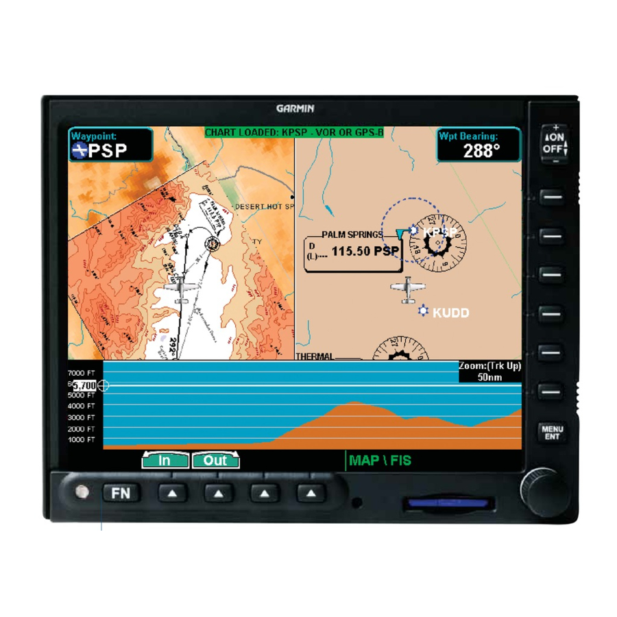
Page 43: Split Screen (Split) Function
Detailed Operation Split Screen Split Screen (SPLIT) Function The zoom scale and map orientation are displayed in the upper right corner of the profile display. The Split Screen capability allows you to display up to two enabled functions side by side. Press the MENU ITEM key next to the desired map to highlight the selection. -
Page 44: Tas / Tcad Traffic (Traf) Function
TAS /TCADTraffic (TRAF) Function Symbology Traffic is shown with either the relative or absolute The GMX 200 I/O Traffic model supports interfaces altitude indicated above or below the target symbol. If to third party traffic sensors. The traffic function, when the traffic is below or equal to your ownship altitude,... -
Page 45: Vert Smart Key (Tas)
Shown in yellow in the lower right corner. TAS Data Time-Out Traffic Alert thumbnail GMX 200 is not receiving labels from the TAS unit. Vert Smart Key (TAS) Shown in yellow in the lower right corner. The Vertical Mode (Vert) “smart” key is used to No Bearing Advisories select the vertical filtering mode for the TAS unit. -
Page 46: Tcad 9900B Menu Options
Detailed Operation TAS/TCAD Traffic TCAD 9900B Menu Options Shield Heights This allows the shield heights to be adjusted for the Altitude Option (Relative/Pressure) En Route, Standard, and Terminal shield modes. See The Altitude option lets you select between relative the TCAD operator’ s manual for additional details. and pressure altitude in hundreds of feet. -
Page 47: Ads-B Traffic (Traf) Function
Detailed Operation ADS-B Traffic ADS-B Traffic (TRAF) Function The ADS-B Traffic Function allows you to view other traffic in the area, when installed with a UAT data link radio. This screen can also show your flight plan. Traffic is shown in relationship to your aircraft. “Smart” keys allow you to zoom in and out, and select an individual traffic target. -
Page 48: Traffic Description
Detailed Operation ADS-B Traffic ADS-B equipment may be certified as an air-to-air ADS-B is intended to be used both in-flight and on system for enhancing situational awareness and as a the airport surface. ADS-B systems should be turned surveillance source for air traffic services. Refer to the “on”... -
Page 49: Tis-B Traffic
Detailed Operation ADS-B Traffic A small up or down arrow next to the identifier air traffic surveillance sensors, typically radar. TIS-B indicates that the traffic is climbing or descending is intended to provide ADS-B equipped aircraft with at a rate of at least 500 feet per minute. The end of a more complete traffic picture in situations where the vector line that extends beyond the point of the not all nearby aircraft are equipped with ADS-B. -
Page 50: Tis-B Limitations
Detailed Operation ADS-B Traffic TIS-B Limitations uplinks data pertaining to transponder equipped aircraft. Aircraft without a TIS-B is NOT intended to be used as a transponder will not be displayed as a collision avoidance system and does not TIS-B target. Always assume that there relieve the pilot’s responsibility to “see are more aircraft in the vicinity of your and avoid”... -
Page 51: Degraded Target
flag will be displayed while the GDL 90 UAT broadcasts When a degraded target is selected via the SELECT the ident. The GMX 200 must be configured to be the key in the Traffic function, no distance to the target is UAT’... -
Page 52: Traffic Option
This is where you enter the ATC-assigned ADS-B (ADS-B Broadcast Options) code. This code entered into the GMX 200 does NOT Selecting Tx Alt allows ADS-B position reports to control the code on Mode A, C, or S transponders. It be transmitted with altitude information. -
Page 53: Set 1200
ADS-B Traffic Menu Items (Page 2) code will revert back to the previously set ADS-B code. Time The GMX 200 must be configured as the UAT’ s control The time interval option sets the amount of time to panel to make this function available. -
Page 54: Altitude Option (Relative/Absolute)
Detailed Operation ADS-B Traffic Traffic Menu Option Page 3 In the “ALL” mode, all targets, regardless of their altitude, are shown. In ±2000 foot mode, only targets The third menu option page of the ADS-B Traf- that are within 2000 feet above or below the ownship fic function lets you select options for the choices of altitude are shown. -
Page 55: Enter Fid
Services – Addressed (TIS-A) function when interfaced to a third party TIS-A sensor. The traffic function, when interfaced to the Garmin GTX 330 is capable of displaying traffic targets supplied by that sensor. Stan- dard TCAS-type symbology is used and several menu options are available for adjusting traffic presentation... -
Page 56: Traffic Depiction
TIS-A Menu Options The GMX 200 displays the current operating mode when the MENU key is pressed. Alert Hot Key (TA Prompt) When selected and viewing another function, this... -
Page 57: Operate/Standby
“TIS Unavailable” to indicate the TIS-A sensor is operating, but outside of TIS-A service coverage. The GMX 200, when installed with a control wire to the GTX 330, controls the TIS-A sensor operating “TIS Standby” to indicate the TIS-A sensor is in mode. -
Page 58: Flight Plan (Fpl) Function
Detailed Operation Flight Plan Flight Plan (FPL) Function Use the Flight Plan function to view details about your flight plan route. Press the UP/DOWN arrow “smart” keys to step through the waypoints in your flight plan. Press the INFO key to view information about the waypoint. - Page 59 Detailed Operation Flight Plan Flight Plan Information (PDX selected) Each press the Info function key will step through the available pages of Waypoint Information.
-
Page 60: Terrain (Ter) Function
The Terrain Function shows a map of the terrain in the area relative to your airplane’ s position and shown below. altitude. The GMX 200 has a standard internally based terrain function. The GMX 200 also supports an exter- nal TAWS sensor. When the external TAWS sensor is connected, it replaces the GMX 200’... -
Page 61: Terrain Option Page
Detailed Operation Terrain TRK Up Arc/TRK Up 360 Custom Map and in the Terrain function. Use the IN and OUT keys at the bottom of the screen to zoom in The Terrain function display is always in the Track and zoom out. The zoom scale is shown in the lower Up mode. -
Page 62: External Taws-Based Terrain Display
TAWS Pop-Up Modes information. NOTE: When the GMX 200 is configured for an The GMX 200 will detect TAWS based terrain external Terrain Awareness and Warning System alerts and will force a pop-up of the Terrain Function (TAWS), the “Baro”... -
Page 63: Uat Flight Information Service (Fis) Function
The GMX 200 can display weather A cyan checkerboard pattern indicates that no data from multiple sources. is available for that area, and rainfall in that area is unknown. -
Page 64: Text Display
Detailed Operation UAT - FIS Press the Text key to select the Text (Text) Text Display sub-function. FIS text messages are available on the text display Press the or function smart keys, or use and include METARs and TAFs. Messages are com- the rotary knob, to move up or down the FIS posed of four parts: message type, location, time, and category list to highlight TAF or METAR. -
Page 65: Gdl 69/69A Flight Information Service (Fis) Function
Refer to the XM Satellite Radio web site for a description of the subscription options. The GMX 200 provides options via the menu item keys for all sup- Weather in Current Function Limited to 20 nm or more ported functions, even those that are not available for each subscription level. -
Page 66: Nexrad Description
Detailed Operation GDL 69/69A - FIS NEXRAD Limitations upper altitude. Press the TFR Lbl key to toggle the TFR Identifier Labels on and off. TFRs are drawn on Certain limitations exist regarding the NEXRAD the FIS page when provided by the FIS sensor and can radar displays. -
Page 67: Current
Detailed Operation GDL 69/69A - FIS NEXRAD When enabled, NEXRAD weather information is shown. Composite data from all of the NEXRAD radar sites in the United States is shown. This data is com- posed of the maximum reflectivity from the individual radar sweeps. -
Page 68: Metars
Detailed Operation GDL 69/69A - FIS Echo Tops, and Winds Aloft are not available. NEXRAD animation detail showing image age METAR Legend When Nexrad animation is turned on, all other enabled weather products are disabled. Only images received from the GDL 69/69A since power was applied are displayed. -
Page 69: Gdl 69/69A Fis Current Menu
Detailed Operation GDL 69/69A - FIS GDL 69/69A FIS Current Menu Page 2 animation is turned on, Coverage, METARs, Lightning, Cell Move, Echo Tops, and Winds Aloft are not avail- The second menu option page of the Current FIS able. Selecting Nexrad Animation will disable CT On function lets you select options for the choices of: and CT Animate. -
Page 70: Echo Tops
Detailed Operation GDL 69/69A - FIS Echo Tops Winds Aloft The Winds Aloft selection provides the pilot with Echo Tops indicate the location, elevation, and the wind speed and direction. The winds at a given direction the highest radar echo. This is typically asso- altitude are selected in the Winds Aloft Alt menu item. -
Page 71: Tfr Label
Detailed Operation GDL 69/69A - FIS TFR Label Legend Press MENU/ENTER key and then press the TFR Press MENU/ENTER key and then press the Lbl key to toggle the TFR Identifier Labels on and off. Legend key to display the legends describing the The TFR Identifier Labels note the TFR number and graphic display coding. -
Page 72: Map Detail
Detailed Operation GDL 69/69A - FIS County Warnings Legend AIRMET/SIGMET Legend NEXRAD Legend Freezing Levels Legend City Forecast Legend Cloud Tops Legend Echo Tops Legend Winds Aloft Legend METAR Legend Map Detail Press MENU/ENTER key and then press the Map Detail key to choose between the display of No Overlays, the Base Map, or Map and Nav Aids. -
Page 73: Forecast
GDL 69/69A - FIS Forecast pass certain age thresholds. A product time aging table is shown on the next page. For a GMX 200 that does Weather forecast information is provided for an not have time available from a GPS receiver, age is... -
Page 74: Surface Analysis
Detailed Operation GDL 69/69A - FIS Surface Analysis When enabled, the Surface Analysis forecast shows frontal lines indicating weather fronts and the direc- tion they are moving. High and Low pressure centers are noted with a large H or L. Forecasts are available for intervals of current, 12, 24, 36, and 48 hours. -
Page 75: Airmet
Detailed Operation GDL 69/69A - FIS Press the Next Page key to display the next page of menu items. GDL 69/69A FIS Forecast Menu Page 2 The second menu option page of the Forecast (Fcst) FIS function lets you select options for the choices of: Freezing Levels, County Warnings, Cyclones, TFR Labels, and Label. -
Page 76: Cyclone
Detailed Operation GDL 69/69A - FIS XM FIS County Warnings Legend Press the or arrow keys to display the legends for the selected services. Press Done to turn the Legends off. Cyclone XM FIS Forecast Menu Item Page 3 This product is not available at this time. -
Page 77: Text
Detailed Operation GDL 69/69A - FIS Text Selecting Categories and Messages Press the or function smart keys to move The Text sub-function displays text messages of the up or down the FIS category list. The selected available weather information. Use the function smart category is highlighted. -
Page 78: Sorting Metar, Taf, And Tfr Text Messages
Detailed Operation GDL 69/69A - FIS Sorting METAR, TAF, and TFR Text Messages minimum and maximum altitude, and Notam ID. If TFR text extends beyond the page size, no scrolling is Displayed text products can be sorted by distance available. from your present position (Nearest Pos), distance Press the FN key and then the FIS function key from destination (Nearest Dest), or alphabetically... -
Page 79: Status
Available means the product is a part of your chosen subscription level and the GMX 200 has data that can be displayed. A time stamp will indicate the last received product time, which is the time the product was generated for transmission. -
Page 80: Activation
The ID(s) is attached to this instruction sheet and printed on a label on the back of the unit. The IDs can also be retrieved through the GMX 200 in the Activa- tion page of the Status sub-function. Contact your dealer or customer service if you are unable to locate the radio hardware IDs. -
Page 81: Lightning Strikes (Lt) Function
Detailed Operation Lightning Lightning Strikes (LT) Function The Lightning Strike function allows you to view lightning strikes that are reported by an L3 WX500 Stormscope Weather Mapping Sensor. The “T” marks are used as reference marks to aid in locating strikes in reference to your position. -
Page 82: Cell
Detailed Operation Lightning Cell Self-Test Only lightning strikes associated with a group, or The Self-Test option performs a number of tests on cell, of strikes are displayed. the operation of the WX500 and provides a report of its status. Heading Stabilization Noise Monitor The Heading Stabilization function of the WX500 can be turned on or off with this selection. -
Page 83: Chartview (Chart) Function (Optional)
• When viewed as a dynamic overlay on the using a home PC-based data loader. Custom/IFR Map, the chart will be properly geo- The GMX 200 ChartView feature does not cur- referenced with respect to the base map. Orienta- rently represent a sole replacement for the paper chart tion (track up, north up, etc.), zoom scale, and... -
Page 84: Chart Data Source
Jeppesen JeppView™ product approach charts for the same airport). An approach are available for loading onto the GMX 200 platform. chart will be displayed as an overlay when the follow- These consist of approaches, SIDS, STARS, airspace ing conditions are met: charts, and airport surface diagrams. -
Page 85: Loading The Approach Chart
The GMX 200 performs a complex filtering process that eliminates airports and associated approach charts that are not geo-referenced, based on present position. -
Page 86: Viewing The Chart As An Overlay
Detailed Operation ChartView way down or all of the way up), the zoom scale will be calculated to maintain the active waypoint of your GPS receiver on the screen at all times. When an approach chart is loaded and being displayed, the auto zoom mode will limit the low-end Selecting an Airport in the IFR Function zoom level to 5 nm as the current waypoint is being... -
Page 87: Chartview Function
Detailed Operation ChartView The ChartView Function will retain the last view set and will not change the chart, zoom level, or pan setting when the function is exited and re-entered, allowing it to operate similar to a physical chart manual. An exception to this is when a chart is loaded in the Custom or IFR Map functions. -
Page 88: Menu Items
Detailed Operation ChartView Menu Items Press FN and then CHART. Press MENU/ENTER and then the Menu Item key for the desired function. Selecting the airport for a Chart in the ChartView Function View the chart.Adjust the zoom level using the In or Out keys. -
Page 89: Select Airport
Detailed Operation ChartView Select Airport View Loaded The Select Airport operation allows the airport of The Select Loaded operation allows the currently interest to be selected from a pop-up list. The airports loaded chart to be selected for viewing. This is typically presented in the list are determined based on the des- done if a given chart was LOADED from the Custom/ tination waypoint as the first entry, and a nearest type... -
Page 90: Airport Surface Charts
Detailed Operation ChartView Airport Surface Charts working with surface charts. Airport surface charts provide a graphical presen- Viewing Surface Charts tation of the airport surface area (runways, taxiways, The airport surface charts are treated similarly buildings, towers, and other objects), within the to approach type charts in that they can be viewed immediate airport vicinity. -
Page 91: Operational Considerations
Detailed Operation ChartView approach procedure is not being flown. At this point, When an approach chart is loaded and being the approach chart is unloaded and the airport surface flown, and the aircraft ground speed drops below the chart is displayed. While on the ground, airport surface air/ground transition speed (set in the SYS Function), charts will take priority over any loaded approach it is assumed that a landing has been performed. -
Page 92: Typical Operational Scenario
Detailed Operation ChartView Typical Operational Scenario The following scenarios makes the assumption that: • The appropriate charts are available and geo-refer- enced • The default ground zoom level is set to 0.5 nm • The default air zoom level is set to “AUTO” •... -
Page 93: Radar (Radar) Function
The modes and features supported by the GMX 200 for each of the radar heads are detailed in the following table. Review the Limitations section in the front of this guide for the limitations that apply Rotary knob Adjusting Tilt Values to the radar data. -
Page 94: Test Mode
Pressing the TEST key while in the Standby mode places the radar in the Test mode. The radar then Manual Gain (GWX 68 only) sends a test pattern that is displayed on the GMX 200. Activating the Gain - and Gain + keys will result Weather Mode in changing the blue Manual Gain bar displayed above the key labels. -
Page 95: Range Control
Detailed Operation Radar Bearing Control (GWX 68/ART2000/2100 only) The Bearing (BRG) control is used to adjust the current bearing angle of the radar head when vertical sweeping is being performed. While in the Vertical mode, the bearing is adjusted using the Brg and Brg ... -
Page 96: Hold Control
Detailed Operation Radar For example, if horizontal scanning is occurring, a cursor line can be activated to pre-select a specific bearing to a weather cell of interest. Once selected, changing the scan mode to vertical will automatically Automatic Radar Gain Control (GWX 68) set the bearing of the vertical sweeps to the bearing previously indicated by the cursor line. -
Page 97: Sector Scan (Gwx 68 Only)
Detailed Operation Radar Sector Scan (GWX 68 only) Sector scanning is only available in the GWX 68. Pressing the SCTR/SCAN key toggles between Sector Scan (SCTR) and Normal Scan (SCAN). Selecting Sector Scan reduces the scan angle to ±10° in horizon- tal scanning and ±5°... - Page 98 Detailed Operation Radar Fault Message Description Action Electrical fault with the radar hardware Power off the radar. The radar needs service. or the aircraft power bus. 400 Hz A previously available analog 400 Hz An external sensor has failed and needs service. reference signal is no longer detected.
-
Page 99: Garmin Gwx 68 Radar Description
The returned signal is then The Garmin GWX 68 Airborne Color Weather processed and displayed on the GMX 200 MFD. Radar is a four color digital pulsed radar with 6.5 Radar detection is a two-way process that requires kilowatts of power. -
Page 100: Radar Signal Attenuation
Detailed Operation Radar ��� �� Radar Beam in Relation to the Curvature of the Earth It is important to understand the concept of the that the radar energy leaving the antenna is inversely antenna beam illumination. The radar beam is much proportional to the square of the distance. -
Page 101: Radar Signal Reflectivity
Detailed Operation Radar Ground Returns unless another cell or a ground target can be seen beyond the heavy cell. The intensity of ground target returns depends upon the angle at which the radar beam strikes the Radar Signal Reflectivity ground target (Angle of Incidence) and the reflective Precipitation properties of that target. -
Page 102: Angle Of Incidence
Detailed Operation Radar Angle of Incidence Operating DISTANCE The angle at which the radar beam strikes the The following information establishes a minimum target is called the Angle of Incidence. Incident angle safe distance from the antenna for personnel near an (“A”) is illustrated below. -
Page 103: Antenna Tilt Setup At Cruise Altitude
Detailed Operation Radar the antenna tilt 4 degrees can help separate ground returns from weather returns in relatively flat terrain. MPEL Boundary This will place the bottom of the radar beam level with the ground. Return the antenna tilt to the previous Center Line of 10.83 ft for 12”... -
Page 104: Weather Mapping And Interpretation
Detailed Operation Radar Weather Mapping and Interpretation Along squall lines, individual cells are in different stages of development. Areas between closely spaced, Weather display Interpretation intense targets may contain developing clouds not When evaluating various target returns on the having enough moisture to produce a return. How- weather radar display, the colors denote rainfall inten- ever, these areas could have strong updrafts or down- sity and rates as shown in the table below. - Page 105 Detailed Operation Radar Squall Line Steep Gradient Hook or Finger Scalloped Edge Cell Irregularities The “Blind Alley”...
-
Page 106: Tornadoes
Detailed Operation Radar shafts are extremely narrow (100 yards or less) and make poor radar targets. In the upper regions of the Tornadoes cell, where ice particles are “dry” (no liquid coating), There is no conclusive radar target return char- target returns are less intense. -
Page 107: Xm Satellite Radio (Xm) Function
Audio entertainment is available through the XM Satellite Radio Service when activated in the optional installation of the GDL 69A. The GMX 200 serves as the display and control head for your remotely mounted GDL 69A. XM Satellite Radio allows you... -
Page 108: Menu
Detailed Operation XM Satellite Radio Menu Page 1 Radio ID The first menu item page of the XM Radio function Each XM radio contains a unique ID that allows lets you select the options for viewing the Radio ID, XM to communicate over the air with the radio. The saving a channel preset, going to the last channel, or owner must activate XM service by providing the selecting preset channels 1 and 2. -
Page 109: Save Preset
Detailed Operation XM Satellite Radio Save Preset Last Channel The Save Preset menu item allows you to store the The Last Channel menu item allows you to return displayed channel into a selected preset position for to the last tuned channel. easy later recall. -
Page 110: Volume
Detailed Operation XM Satellite Radio Volume Channels The Volume control allows you to set the audio The Channel feature is used to navigate through volume level, as well as mute the audio. the channels in the selected category. XM Audio Radio Channel Selection Controls XM Audio Radio Volume Controls In the XM radio function, press the double ... -
Page 111: Categories
Detailed Operation XM Satellite Radio Categories Direct Access Categories of channels, such as Jazz, Rock, or Channels can be accessed directly by entering the News, can be selected to list the available channels for channel number using the smart keys. a type of music or other contents. -
Page 112: Activating Xm Satellite Radio Services
The ID(s) is attached to this instruction sheet and printed on a label on the back of the unit. The IDs can also be retrieved through the GMX 200 in the Radio ID page of the XM Satellite Radio function. -
Page 113: Xm Advisory Messages
Detailed Operation XM Satellite Radio XM Advisory Messages Message Condition Description Check Antenna Antenna not connected The XM antenna(s) or antenna cable are disconnected from the radio. Updating Updating encryption code The encryption code has been changed over the air by XM and the radio has not received the newest code information yet from the XM signal. -
Page 114: System (Sys) Function
Baro-Correction (QNH) can now be entered in Mil- preferences, obtain version information, and perform libars in addition to in. Hg. tests on the operation of your GMX 200. Set Baro Correction Press the FN key and then press the SYS key to (Pressure Altitude Source only) reach the System functions. -
Page 115: Initial En Route Zoom Scale, Initial Ground Zoom Scale, And Transition Speed
• Air-to-Ground mode (Landing) 480-series GPS navigator. When enabled and the GMX 200 is in Auto Zoom mode, the GMX 200 will auto- When the aircraft transitions from Ground-to-Air, matically set the zoom scale to that used on the GNS the zoom scale is automatically set to a user selected 480-series navigator. -
Page 116: Altitude Units
NIC and NACP are displayed. Additional Features The Additional Features window shows optional features that have been installed. Data Link Status When the GMX 200 is connected to a GDL 90 UAT, the status of the link is displayed. -
Page 117: System Test Pages
Data-link information is monitored as follows: The Test Pattern option displays a number of Name Description patterns and colors to test the GMX 200 display. Use Heart-Beat from the UAT this option to verify proper operation of the display or data-link radio when contacting Customer Service. -
Page 118: Test Pattern 2
Detailed Operation System Test Pattern 2 Test Pattern 2 shows the gamut of colors available on the GMX 200 display. System Test Pattern 2... -
Page 119: Troubleshooting
If you cannot correct the problem, contact your dealer. If your dealer is unavail- able, contact the Garmin factory at the address and phone number listed in the preceding section. Be sure to have the information from the System Info page and the data card available before you contact your dealer or the factory. - Page 120 You must have the ADS-B system installed and configured. If you do have an ADS-B system, check the antennas and other components for proper operation. Have dealer/installer check for proper GMX 200 setup. “Special Terrain” message GMX 200 configuration Must be set to normal.
-
Page 121: Gdl 69/69A Fis Legends
Appendix GDL 69/69A FIS Screens GDL 69/69A FIS Legends The following legends describe the graphical information on the GDL 69/69A FIS displays. AIRMET/SIGMET Legend NEXRAD Legend Cloud Tops Legend City Forecast Legend METAR Legend Echo Tops Legend County Warnings Legend Freezing Levels Legend Winds Aloft Legend... -
Page 122: Sample Gdl 69/69A Fis Displays
Appendix GDL 69/69A FIS Screens Sample GDL 69/69A FIS Displays The following displays provide examples of information shown in the GDL 69/69A FIS function. XM FIS METARs XM FIS with NEXRAD Weather and Legend XM FIS Echo Tops XM FIS Radar Coverage XM FIS City Forecast XM FIS Winds Aloft... -
Page 123: Specifications
Display: 6.5 in. diagonal (16.5 cm) 65,535-color display with backlighting (640 x 480 pixels) Power 14 VDC GMX 200: 2.24 A Max GMX 200 I/O: 2.45 A Max 28 VDC GMX 200: 1.16 A Max GMX 200 I/O: 1.32 A Max Environmental Temp. -
Page 124: Care Information
Care Information Care Information Cleaning the Unit Your GMX 200 has a durable display, but reason- able care must be taken to maintain its performance and life. To remove stains, smudges, fingerprints, and so forth, we recommend these cleaning methods. If the first method fails to remove the problem, try the next... -
Page 125: Glossary
Speed —Display rate of travel in miles/kilometers/ upon data presented by the GMX 200. nautical miles per hour. Altitude—Height above mean sea level (MSL). -
Page 126: Abbreviations
En Route ETP — Echo Tops The following is a list of abbreviations and EULA — End User License Agreement acronyms used on the GMX 200 and their meanings: ABV — Above °F — Degrees Fahrenheit ADS-B — Automatic Dependent FID —... - Page 127 Appendix Abbreviations kg — Kilograms NEXRAD — Next Generation RADAR kHz — Kilohertz nm — Nautical Miles km — NOTAM — Notice to Airmen Kilometers kph — Kilometers Per Hour NRM — Normal kt — Knots OBS — Omnibearing Selector LAT/LON —...
- Page 128 Appendix Abbreviations Warning System TCAD — Traffic/Collision Avoidance Device TCAS — Traffic Alert/Collision Avoidance System TER — Terrain TFR — Temporary Flight Rules TIS-A — Traffic Information Services - Addressed TIS-B — Traffic Information Service - Broadcast TRAF — Traffic TRANS —...
-
Page 129: License And Registration Information
FAX: (913) 397-8282 online registration today! Have the serial number of http://www.garmin.com your GMX 200 handy and connect to the Garmin Web site (www.garmin.com). Look for the Product Registra- Be prepared to offer the following information tion link on the home page. Also, be sure to record about the installation: your serial number in the space provided to the left. -
Page 130: Limited Warranty
Or, call Garmin Customer Service at one of the numbers listed to the left for shipping This Garmin product is warranted to be free from instructions and an RMA tracking number. The unit defects in materials or workmanship for 24 months from the date of purchase. -
Page 131: Index
Appendix Index Backlight 111 Symbols Back course 21, 113 Barometer 18, 28, 30, 49 400 Hz 86 Barometric Correction 49 Barometric correction 9, 49, 102 Barometric Pressure 9, 114 Baro keys 49 Abbreviations 114 Basic operation 8, 75 Absolute 25 Bearing 12, 18, 20, 28, 30, 33, 46, 81, 82, 83, 84, 85, 113 Accessories iv Bearing cursor 81, 84... - Page 132 Index Contact customer service 5, 8, 68, 100, 112, 117 Flight ID 42, 114 Contact XM radio 100 Flight plan 7, 18, 27, 30, 42, 46, 49, 59, 64, 69 Controls 4 Forecast 61 County 63 Forecast Time 62 County warnings 60, 61, 64, 109 FPGA 86 Course 18, 21, 27, 30, 42, 49, 55, 59, 64, 69, 113 Freezing Levels 60, 61, 63, 109...
- Page 133 Index IHAS 1, 32 ILS 7, 20, 21, 114 Nav 7, 21 Info 17, 74, 104 Nav/Com 20 Initial Zoom level 16, 103 Nav Data 18, 19, 27, 28, 30, 46 Intersection 22 NDB 20, 22, 115 Invert 28, 30, 79 NexRad 54, 55, 58, 60, 61, 110, 115 No-bearing 33 Noise monitor 70...
- Page 134 Index Radar range control 83 Split Screen 1, 2, 9, 31 Radar test 82 Stabilization 69, 70, 81, 85, 86, 115 Radio ID 68, 96, 100 Standby 33, 40, 45, 81, 115 Rain 51, 54 STARS 72, 115 RAM 86 Start Up 8, 16, 107 Range ring 42, 108 Status 6, 7, 33, 45, 53, 67, 70, 85...
- Page 135 Index Thumbnail 11, 26, 32, 44 Thumbnail activation 11 Warranty ii, 118 Thunderstorm 54, 63 Waters 23 Tilt Control 81, 83 Weather v, 81, 82, 100, 105, 109, 110 Time 26, 33, 37, 41, 52, 56, 60, 61, 62, 67, 113, 114, 117 Key 17 TIS 6, 11, 12, 37, 39, 43 XM Radio 53, 96...
- Page 136 Index...
- Page 138 © 2006 Garmin Ltd. or its subsidiaries Garmin International, Inc. 1200 East 151 Street, Olathe, Kansas 66062, U.S.A. Garmin (Europe) Ltd. Unit 5, The Quadrangle, Abbey Park Industrial Estate, Romsey, SO51 9DL, U.K. Garmin Corporation No. 68, Jangshu 2 Road, Shijr, Taipei County, Taiwan www.garmin.com...
Need help?
Do you have a question about the GMX 200 and is the answer not in the manual?
Questions and answers