Garmin GMA 340 Installation Manual
Hide thumbs
Also See for GMA 340:
- Maintenance manual (51 pages) ,
- Pilot's manual (12 pages) ,
- Supplemental operation manual (10 pages)

Related Manuals for Garmin GMA 340


Summary of Contents for Garmin GMA 340
-
Page 1: Installation Manual
GMA 340 AUDIO PANEL INSTALLATION MANUAL (GMA 340, GMA 340H, GMA 340 DUAL ADF) (GMA 340 and GMA 340 Dual ADF Shown) Garmin International, Inc. 1200 E. 151 Street Olathe, KS 66062 USA 190-00149-01 Revision L June 2003... - Page 2 Garmin. Garmin hereby grants permission to download a single copy of this manual and of any revision to this manual onto a hard drive or other electronic storage medium to be viewed and to...
-
Page 3: Table Of Contents
2.3.1 Location Considerations......................... 2-1 2.3.2 Antenna Installation........................2-1 2.3.3 Antenna Cable Installation ......................2-1 2.3.4 Installation Approval Considerations for Pressurized Aircraft ............2-2 2.4 GMA 340 INSTALLATION......................2-2 2.5 REAR CONNECTIONS ........................2-3 2.5.1 Location............................2-3 2.5.2 Audio Shield Termination ......................2-5 2.5.3 Noise............................... -
Page 4: Paragraph Page
3.1.13 Marker Beacon Receiver ........................ 3-6 APPENDIX A CERTIFICATION DOCUMENTS A.1 CONTINUED AIRWORTHINESS ....................A-1 A.2 ENVIRONMENTAL QUALIFICATION FORM ................A-4 APPENDIX B INSTALLATION DRAWINGS B.1 GENERAL ............................B-1 APPENDIX C STC PERMISSION C.1 GENERAL ............................C-1 Page ii GMA 340 Installation Manual Rev. L 190-00149-01... - Page 5 3-1 GMA 340 FRONT PANEL....................... 3-1 B1 GMA 340 OUTLINE DRAWING ....................B-3 B2 CONNECTOR/RACK KIT DRAWING ..................B-5 B3 GMA 340 RECOMMENDED PANEL CUTOUT DIMENSIONS ..........B-7 B4 J1 INTERCONNECT WIRING DIAGRAM ..................B-9 B5 J2 INTERCONNECT WIRING DIAGRAM ..................B-11 B6 J1 INTERCONNECT WIRING DIAGRAM ..................B-13 B7 J2 INTERCONNECT WIRING DIAGRAM ..................B-15...
- Page 6 The table is current at the time of publication of this manual (see date on front cover) and is subject to change without notice. Authorized Garmin Sales and Service Centers are encouraged to access the most up-to- date bulletin and advisory information on the Garmin Dealer Resource web site at www.garmin.com using their Garmin-provided user name and password.
-
Page 7: Introduction
PA announcements. The PA function is pilot selectable. The GMA 340 is FAA TSO approved to C50c and C35d and JTSO approved to C50c and 2C35d. Also standard is the marker beacon receiver with dual sensitivity and audio muting with automatic re-arming. 14V or 28V operation, including the full rated range of headphone and speaker output power, is available without the requirement for external voltage converters or dropping resistors. -
Page 8: Specifications
Receiver inputs: 5 (6 in Dual ADF version) Unswitched inputs: 2 Input impedance: 500 (800 DME input in Dual ADF) Input isolation: 60 dB minimum Special functions: Fail-safe operation MASQ processing Page 1-2 GMA 340 Installation Manual Rev. L 190-00149-01... -
Page 9: Equipment
011-00678-00Rack Backplate, GMA 340 • 115-00262-00SMP, Install Rack, GMA 340 (The installation kit is the same for the GMA 340, GMA 340H and GMA 340 Dual ADF) INSTALLATION ACCESSORIES • Marker beacon antenna kit (P/N 010-10175-00). [Note: A marker beacon antenna approved to TSO C35( ) that has been installed to meet the requirements of this manual may be approved for use with the GMA 340]. -
Page 10: Additional Equipment Required
• Stereo headphone jacks (up to 6), microphone jacks (up to 6), 3.5mm stereo jacks (up to 2), and insulating washers for all. Page 1-4 GMA 340 Installation Manual Rev. L 190-00149-01... -
Page 11: Limited Warranty
Garmin retains the exclusive right to repair or replace the unit or software or offer a full refund of the purchase price at its sole discretion. SUCH REMEDY SHALL BE YOUR SOLE AND EXCLUSIVE REMEDY FOR ANY BREACH OF WARRANTY. - Page 12 This page intentionally left blank. Page 1-6 GMA 340 Installation Manual Rev. L 190-00149-01...
-
Page 13: Installation
If the unit is damaged, notify the carrier and file a claim. To justify a claim, save the original shipping container and all packing materials. Do not return the unit to Garmin until the carrier has authorized the claim. -
Page 14: Installation Approval Considerations For Pressurized Aircraft
4. Turn the Allen wrench clockwise until the unit is secured in the rack. Continue turning until tight, but do not over-tighten. 5. To remove the unit from the rack, turn the Allen wrench counterclockwise until it disengages from the rack. Page 2-2 GMA 340 Installation Manual Rev. L 190-00149-01... -
Page 15: Rear Connections
Location The GMA 340 has two 44 pin connectors located at the rear of the unit, designated J1 and J2. J1 and J2 pin assignments are given in table 2-1. When viewed from the back of the rack, J1 and J2 look like the following: Figure 2-1. - Page 16 Pass 1 Mic Return Ext Blue Lamp; O Pass 2 Mic Ext Amber Lamp; M Pass 2 Mic Return Middle Mkr Sens Pass 3 Mic Pass Headset L Pass 3 Mic Return Page 2-4 GMA 340 Installation Manual Rev. L 190-00149-01...
-
Page 17: Audio Shield Termination
615725 M81969/1-04 Table 2-2. Recommended Crimp Tools NOTE Non-Garmin part numbers shown are not maintained by Garmin and consequently are subject to change without notice. 2.5.2 Audio Shield Termination The audio shield wires should be terminated at the rear of the unit to the screws between J1 and J2 as shown in figure 2-2. -
Page 18: Noise
Apply power to the unit by rotating the pilot intercom knob (5) clockwise. The GMA 340 test button (17) checks the internal LED annunciators and marker beacon LEDs (1). Press TEST to confirm operation of the LEDs. Cover the photocell (19) with a finger and observe that the LED annunciators dim automatically. -
Page 19: Failsafe Operation Check
4. Check Pilot and Copilot ICS positions for isolation and proper operation of volume and squelch controls (5, 6, 7 and 8). 5. Press the PA button (11). Verify that microphone audio is heard over the speaker. GMA 340 Installation Manual Page 2-7 190-00149-01... -
Page 20: Aircraft Receivers Check
When audio levels applied to Music 1 and Music 2 inputs are increased by 20 dB, the amplification may also increase unwanted audio noise. See note 17 in figures B5 and B7 and refer to Garmin Service Bulletins 0113 and 0210. 1. Set the intercom to the ALL mode [Crew (9) and Pilot (10) LEDs off.] 2. -
Page 21: Adjustments
LOW sensitivity setting also. If the HIGH sensitivity setting is adjusted, then the LOW sensitivity setting should be checked and adjusted afterwards, if needed. If your GMA 340 top cover does not have the marker beacon sensitivity adjustment access holes as indicated in figure 2-3, and you need to adjust the sensitivity, contact Garmin for instructions. -
Page 22: Access Hole Location
MKR HI Sense A/C radio SPKR level Pilot PA MIC SPKR level Copilot PA MIC SPKR level Marker audio level Music1 mute trip level Figure 2-3. Access Hole Location (Top View) Page 2-10 GMA 340 Installation Manual Rev. L 190-00149-01... -
Page 23: Operation
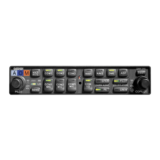
SECTION 3 OPERATION OPERATION Figure 3-1. GMA 340 Front Panel 3.1.1 Front Panel Controls Marker Beacon Lights Marker Beacon Receiver Audio Select/Mute Button Marker Beacon Receiver Sensitivity Indicator LEDs Marker Beacon Receiver Sensitivity Selection Button Unit On/Off, Pilot Intercom System (ICS) Volume... -
Page 24: On, Off, And Failsafe Operation
On, Off, and Failsafe Operation The GMA 340 is powered off when the left small knob (figure 3-1, item 5) is rotated fully CCW into the detent. To turn the unit on rotate the knob clockwise past the click. The knob then functions as the pilot’s ICS volume control. -
Page 25: Split Com
Com Swap Function The GMA 340 allows the use of a remote mounted switch (typically on the yoke) to alternately transfer the active microphone back and forth between COM 1 and COM 2. The remote switch should be a momentary type, connected between J2 pin 20 (SWAP*) and J2 pin 21 (SWAP return). -
Page 26: Pa Function
3.1.10 Auxiliary Entertainment Inputs The GMA 340 and 340H provide two stereo entertainment inputs: MUSIC 1 and MUSIC 2. The 340 Dual ADF has only MUSIC 1. MUSIC 1 is soft-muted during all aircraft radio activity and normally during ICS activity. -
Page 27: 3.1.12 Mono/Stereo Headset
Use of a monaural headset in a stereo jack shorts the right headset channel output to ground. A person listening on a monaural headset will hear only the left channel from the GMA 340 in both ears. If a monaural headset is used at one of the passenger positions, any other passenger listening on a stereo headset will hear audio in their left ear only, unless their headset has a stereo/mono switch and it is set for mono. -
Page 28: 3.1.13 Marker Beacon Receiver
(see figure 2-3). The GMA 340’s marker beacon receiver controls are located on the left side of the front panel [(1) through (4)]. The SENS button (4) selects either high or low sensitivity as indicated by the HI or LO LED being lit. Low sensitivity is used on ILS approaches while high sensitivity allows operation over airway markers or to get an earlier indication of nearing the outer marker during an approach. -
Page 29: Certification Documents
ICA. Following is suggested ICA for a Garmin GMA 340 Audio Panel installation. Some of the checklist items do not apply, in which case they should be marked “N/A” (Not Applicable). In this sample, square braces are used to indicate instances where explicit words should be substituted. - Page 30 4. Servicing Information 5. Maintenance Instructions Maintenance of the GMA 340 Audio Panel is ‘on condition’ only. Periodic maintenance is not required. Refer to the GMA 340 Audio Panel Maintenance Manual. 6. Troubleshooting Information Refer to the GMA 340 Audio Panel Maintenance Manual.
- Page 31 43.9. This entry records the major alteration and identifies the original ICA location (e.g., Block 8 of FAA Form 337, dated ______) along with a statement that the ICA is now part of the aircraft’s inspection/maintenance requirements. GMA 340 Installation Manual Page A-3 190-00149-01...
-
Page 32: Environmental Qualification Form
ENVIRONMENTAL QUALIFICATION FORM NOMENCLATURE: GMA 340 Audio Panel TYPE/MODEL/ PART NO.: 010-00152-( ), which includes all 011-00401-( ); 340H is -01; Dual ADF is-20. TSO-C50c, TSO-C35d Class A, JTSO-C50c, JTSO-2C35d MANUFACTURER’S SPECIFICATION AND/OR OTHER APPLICABLE SPECIFICATION: 004-00054-00 MANUFACTURER: Garmin International ADDRESS: 1200 E. -
Page 33: Installation Drawings
This section contains the following installation drawings: • B1, GMA 340 Outline Drawing • B2, Connector/Rack Kit Drawing • B3, GMA 340 Recommended Panel Cutout Dimensions • B4, J1 Interconnect Wiring Diagram • B5, J2 Interconnect Wiring Diagram • B6, J1 Interconnect Wiring Diagram •... - Page 34 This page intentionally left blank Page B-2 GMA 340 Installation Manual Rev. L 190-00149-01...
-
Page 42: C.1 General
APPENDIX C STC PERMISSION GENERAL Consistent with N8110.69 or Order 8110.4, Aviation Authority approved installers are hereby granted permission to use STC #SA00710WI data to modify aircraft. GMA 340 Installation Manual Page C-1 190-00149-01 Rev. L... - Page 43 Page C-2 GMA 340 Installation Manual Rev. L 190-00149-01...
Need help?
Do you have a question about the GMA 340 and is the answer not in the manual?
Questions and answers