Lincoln Electric LN-25 PRO Operator's Manual
Arc welding and cutting equipment
Hide thumbs
Also See for LN-25 PRO:
- Service manual (104 pages) ,
- Operator's manual (45 pages) ,
- Operator's manual (24 pages)
Table of Contents
Advertisement
Quick Links
IM10031-A
LN-25 PRO
TM
November, 2010
For use with machines having Code Number: 11620, 11621, 11716, 11717
Safety Depends on You
Lincoln arc welding and cutting
equipment is designed and built
with safety in mind. However, your
overall safety can be increased by
proper installation ... and thoughtful
operation on your part. DO NOT
INSTALL, OPERATE OR REPAIR
THIS EQUIPMENT WITHOUT
READING THIS MANUAL AND
THE SAFETY PRECAUTIONS
CONTAINED THROUGHOUT.
And, most importantly, think before
you act and be careful.
IP23
IEC 60974-5
OPERATORʼS MANUAL
Copyright © Lincoln Global Inc.
• World's Leader in Welding and Cutting Products •
• Sales and Service through Subsidiaries and Distributors Worldwide •
Cleveland, Ohio 44117-1199 U.S.A. TEL: 216.481.8100 FAX: 216.486.1751 WEB SITE: www.lincolnelectric.com
Advertisement
Table of Contents

Related Manuals for Lincoln Electric LN-25 PRO


Summary of Contents for Lincoln Electric LN-25 PRO
- Page 1 IP23 IEC 60974-5 OPERATORʼS MANUAL Copyright © Lincoln Global Inc. • World's Leader in Welding and Cutting Products • • Sales and Service through Subsidiaries and Distributors Worldwide • Cleveland, Ohio 44117-1199 U.S.A. TEL: 216.481.8100 FAX: 216.486.1751 WEB SITE: www.lincolnelectric.com...
- Page 2 SAFETY WARNING CALIFORNIA PROPOSITION 65 WARNINGS Diesel engine exhaust and some of its constituents The engine exhaust from this product contains are known to the State of California to cause can- chemicals known to the State of California to cause cer, birth defects, and other reproductive harm.
-
Page 3: Electric Shock Can Kill
SAFETY ARC RAYS can burn. ELECTRIC SHOCK can 4.a. Use a shield with the proper filter and cover kill. plates to protect your eyes from sparks and 3.a. The electrode and work (or ground) circuits the rays of the arc when welding or observing are electrically “hot”... - Page 4 SAFETY WELDING and CUTTING CYLINDER may explode SPARKS can if damaged. cause fire or explosion. 7.a. Use only compressed gas cylinders 6.a. Remove fire hazards from the welding area. containing the correct shielding gas for the If this is not possible, cover them to prevent process used and properly operating the welding sparks from starting a fire.
- Page 5 SAFETY PRÉCAUTIONS DE SÛRETÉ 6. Eloigner les matériaux inflammables ou les recouvrir afin de prévenir tout risque dʼincendie dû aux étincelles. Pour votre propre protection lire et observer toutes les instructions et les précautions de sûreté specifiques qui parraissent dans ce 7.
- Page 6 SAFETY Electromagnetic Compatibility (EMC) Conformance Products displaying the CE mark are in conformity with European Community Council Directive of 15 Dec 2004 on the approximation of the laws of the Member States relating to electromagnetic compatibility, 2004/108/EC. It was manufactured in conformity with a national standard that implements a harmonized standard: EN 60974-10 Electromagnetic Compatibility (EMC) Product Standard for Arc Welding Equipment.
- Page 7 SAFETY Electromagnetic Compatibility (EMC) The size of the surrounding area to be considered will depend on the structure of the building and other activities that are taking place. The surrounding area may extend beyond the boundaries of the premises. Methods of Reducing Emissions Mains Supply Welding equipment should be connected to the mains supply according to the manufacturer’s recommenda- tions.
- Page 8 Thank You for selecting a QUALITY product by Lincoln Electric. We want you to take pride in operating this Lincoln Electric Company product ••• as much pride as we have in bringing this product to you! CUSTOMER ASSISTANCE POLICY The business of The Lincoln Electric Company is manufacturing and selling high quality welding equipment, consumables, and cutting equip- ment.
-
Page 9: Table Of Contents
viii viii TABLE OF CONTENTS Page –––––––––––––––––––––––––––––––––––––––––––––––––––––––––––––––––––––––––––––––– Installation........................Section A Technical Specifications .......................A-1 Safety Precautions .......................A-2 Location ..........................A-2 High Frequency Protection ....................A-2 Weld cable Sizes ........................A-2 Analog Control Cable ......................A-3 Cable Connections and Control Cable Connector ...............A-4 Shielding Gas Connection ....................A-4 Wire Drive Configuration ......................A-5 Changing The Gun Receiver Bushing ................A-5 Procedure to Install Drive Rolls and Wire Guides ..............A-5... -
Page 10: Installation
INSTALLATION TECHNICAL SPECIFICATIONS – LN-25™ PRO (K2613-1, K2613-2) INPUT VOLTAGE and CURRENT INPUT VOLTAGE ± 10% INPUT AMPERES 15-110 VDC RATED OUTPUT @ 104°F (40°C) DUTY CYCLE INPUT AMPERES 60% rating 100% rating GEARING - WIRE FEED SPEED RANGE-WIRE SIZE GMAW FCAW GEARING... -
Page 11: Safety Precautions
INSTALLATION SAFETY PRECAUTIONS The handle of the LN-25™ PRO is intended for moving the wire feeder about the work place only. WARNING When suspending a wire feeder, insulate the ELECTRIC SHOCK CAN KILL. hanging device from the wire feeder enclosure. • Turn the input power OFF at the HIGH FREQUENCY PROTECTION disconnect switch or fuse box before attempting to connect or... -
Page 12: Analog Control Cable
Work connection to feeder Work connection from power source 42 VAC to feeder 42 VAC to feeder Reserved Reserved 42 VAC to feeder 42 VAC to feeder Reserved Reserved unused unused Electrode voltage from feeder Electrode voltage to power source LN-25 PRO... -
Page 13: Shielding Gas Connection
INSTALLATION SHIELDING GAS CONNECTION CABLE CONNECTIONS WARNING There is one circular connector for the gun trigger on the front of the LN-25™ PRO. CYLINDER may explode if damaged. • Keep cylinder upright and chained to support. Function Wiring • Keep cylinder away from areas where it may be 5-pin trigger Trigger damaged. -
Page 14: Wire Drive Configuration
INSTALLATION WIRE DRIVE CONFIGURATION 8. Connect the shielding gas hose to the new gun bushing, if required. (See Figure A.2) 9. Rotate the gun bushing until the thumb screw hole CHANGING RECEIVER aligns with the thumb screw hole in the feed plate. BUSHING Slide the gun receiver bushing into the wire drive and verify the thumb screw holes are aligned. -
Page 15: Pressure Arm Adjustment
INSTALLATION 1. Squeeze the release bar on the retaining collar and PRESSURE ARM ADJUSTMENT remove it from the spindle. WARNING 2. Place the spindle adapter on the spindle, aligning the spindle brake pin with the hole in the adapter. ELECTRIC SHOCK can kill. •... - Page 16 INSTALLATION POWER SOURCE TO LN-25™ PRO CABLE CONNECTION DIAGRAMS ACROSS THE ARC SET-UPS CC Power Sources with Output Terminals Always Hot (See Figure A.5) CC Power Source Classics FIGURE A.5 Big Red’s Eagle 10,000 Plus Pipeliner 200D Without Wire Feed module SAE’s Without CV Adapter LN-25™...
- Page 17 INSTALLATION CV Power Sources with Stud Connectors and no Remote/Local Switch. (See Figure A.7) Place CV/CC switch in the feeder in the "CV" position. FIGURE A.7 CV-400 DC-655 Jumper Ranger 250, 250 LPG Ranger 305G, 305D LN-25™ Pro Ranger 10,000 Electrode Ranger 3 Phase Ranger 225GXT...
- Page 18 INSTALLATION CV Power Source with Twist-Mate Connectors and no Remote/Local Switch. (See Figure A.9) FIGURE A.9 Jumper CV-250 CV-300 LN-25™ PRO CV-305 Electrode Work clip Work Description Place CV/CC switch in the feeder in the "CV" position. LN-25™ PRO K2613-1 K2613-2 LN-25™...
-
Page 19: Operation
OPERATION SAFETY PRECAUTIONS GRAPHIC SYMBOLS THAT APPEAR ON THIS MACHINE OR IN THIS MANUAL READ AND UNDERSTAND ENTIRE SECTION BEFORE OPERATING MACHINE. INPUT POWER WARNING • ELECTRIC SHOCK CAN KILL. Unless using COLD FEED fea- ture, when feeding with gun trig- ger, the electrode and drive mechanism are always electri- cally energized and could... -
Page 20: Definition Of Welding Terms
OPERATION General Functional Description DEFINITION OF WELDING TERMS The LN-25™ PRO as designed is a simple, robust feeder. Standard features include a calibrated wire feed speed dial, 2 step/trigger interlock switch, CV-CC • Wire Feed Speed switch, Gas Purge and Cold Feed. RECOMMENDED PROCESSES •... -
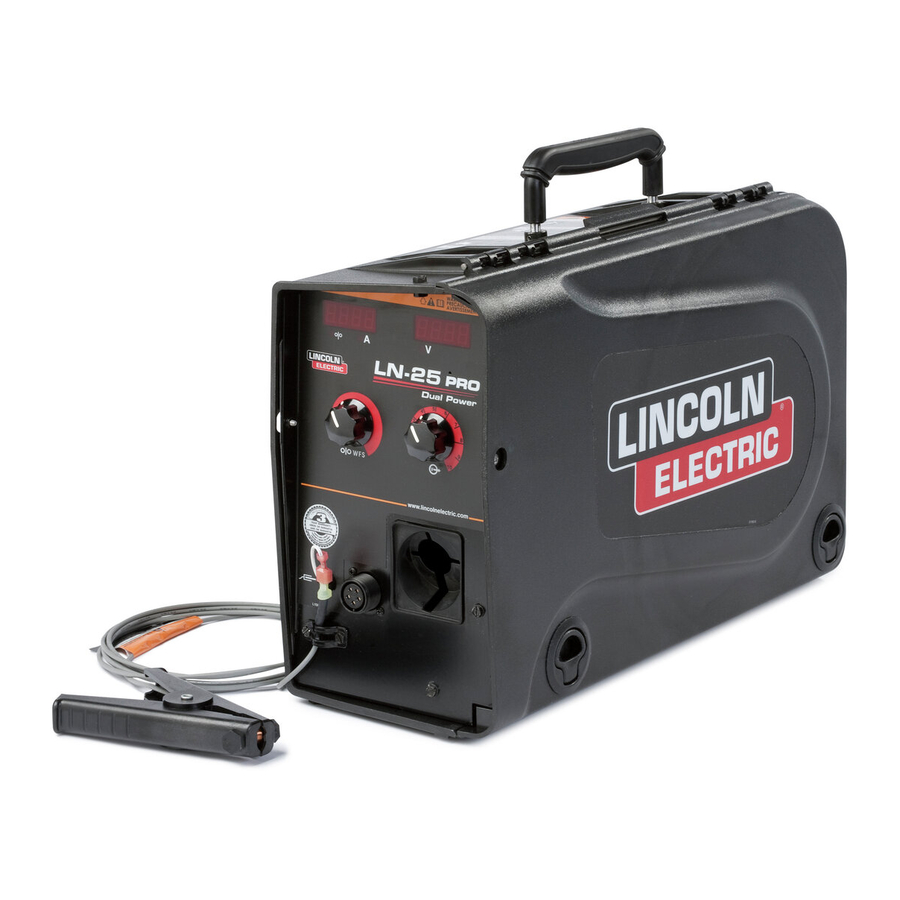
Page 21: Case Front Controls
OPERATION (See Customer Assistance Policy in the front of this Instruction Manual) CASE FRONT CONTROLS (See Figure B.1) FIGURE B.1 ITEM DESCRIPTION Analog Voltmeter Wire Feed Speed Knob 5-pin gun trigger connector Work sense lead Thermal LED, Motor Overload Polarity LED 1. - Page 22 OPERATION 2. WIRE FEED SPEED KNOB Wire Feed Speed, CC Operation The large, calibrated wire feed speed knob makes for easy and accurate adjustment of the wire feed When Across the Arc models are operated with CC speed. The knob rotates 3/4 turn. Turn the knob power sources, the wire feed speed changes as the clockwise to increase the wire feed speed, and arc voltage changes.
- Page 23 OPERATION 3. 5-PIN GUN TRIGGER CONNECTOR 4. WORK SENSE LEAD 5. THERMAL LED, MOTOR OVERLOAD The thermal light illuminates when the wire drive motor draws too much current. If the thermal light illuminates, the wire drive will automatically shutdown for up to 30 seconds to allow the motor to cool.
-
Page 24: Internal Controls
OPERATION INTERNAL CONTROLS FIGURE B.2 ITEM DESCRIPTION 2 Step Trigger Interlock Switch CV / CC Switch Pressure Adjustment Arm Optional Timer Kit (See Accessories Section) Spool Retainer Spindle Brake Gun Bushing Thumb Screw for securing the welding Gun Socket Head Cap Screw for securing the Gun Bushing Drive Hubs Inlet Wire Guide Cold Feed Pushbutton... -
Page 25: Internal Controls Decription
OPERATION INTERNAL CONTROLS DESCRIPTION (See Figure B.2) (See Figure B.2) The CV/CC switch sets the wire feed speed control method for the wire feeder. 2 Step - Trigger Interlock Switch In the CV position, the wire feed speed remains constant during The 2 Step - Trigger Interlock welding. -
Page 26: Constant Current Wire Welding
OPERATION CONSTANT CURRENT WIRE WELDING If the contact tip to work distance is properly main- (See Figure B.3) tained, a satisfactory operating voltage range may be achieved, and a sound weld may result. However, Most semiautomatic welding processes perform better when a welder uses a longer contact tip to work dis- using constant voltage power sources. -
Page 27: Rear Controls
OPERATION REAR CONTROLS: c o n n e c t i o n s I T E M G a s P u r g e P u s h b u t t o n F l o w M e t e r B a l l S h i e l d i n g G a s I n l e t F l o w M e t e r V a l v e O p t i o n a l W a t e r c o o l e d g u n... -
Page 28: Flow Meter
B-10 B-10 OPERATION GAS PURGE PUSHBUTTON POWER-UP SEQUENCE The gas solenoid valve will energize but neither the power source output nor the drive motor will be turned On feeders with analog voltmeters, the thermal LED on. The Gas Purge switch is useful for setting the will briefly light during power-up. -
Page 29: Accessories
ACCESSORIES FACTORY INSTALLED EQUIPMENT • K1500-2 Gun Receiver Bushing. DRIVE ROLL KITS WIRE TYPE ELECTRODE SIZE KP KIT KP1696-030S Steel Wires: .023-.030 (0.6-0.8mm) .035 (0.9mm) KP1696-035S Includes: 2 V groove .045 (1.2mm) KP1696-045S drive rolls and inner .052 (1.4mm) KP1696-052S 1/16 (1.6mm) KP1696-1/16S wire guide. - Page 30 ACCESSORIES K1796-xx AWG 1/0 Co-Axial Power Cable Includes: 1/0 Coaxial weld cable of length "xx". Ends of the weld cable have lug con- nections. Use for Pulse weld- ing. K2593-xx AWG #1 Coaxial Power Cable Includes: AWG #1 Coaxial weld cable of length "xx". Ends of the weld cable have lug connections.
- Page 31 ACCESSORIES K910-1 Ground Clamp Includes: One 300 Amp Ground Clamp. K910-2 Ground Clamp Includes: One 500 Amp Ground Clamp. Gun Receiver Bushing (for guns Includes: Gun receiver bush- K1500-1 with K466-1 Lincoln gun connec- ing, set screw and hex key tors;...
- Page 32 ACCESSORIES Gun Receiver Bushing (for gun Includes: Gun receiver bush- K1500-4 with K466-3 Lincoln gun connec- ing with hose nipple, set screw tors; compatible with Miller® guns.) and hex key wrench. Includes: Gun receiver bushing K1500-5 Gun Receiver Bushing (compatible with hose nipple, 4 guide tubes, with Oxo®...
- Page 33 ACCESSORIES 4. Use a 5/16" nut driver to remove the screws holding INSTALLATION OF THE K590-6 WATER the water cooling cover on the case front of the COOLING KIT inner module and on the rear of the case. WARNING ELECTRIC SHOCK can kill. •...
-
Page 34: Maintenance
MAINTENANCE SAFETY PRECAUTIONS 5. Energize the output circuit of the power source. Adjust the power source output to 20±1 VDC as WARNING measured on the reference meter. ELECTRIC SHOCK can kill. 6. Verify that LN-25™ PRO voltmeter reads between • Turn the input power OFF at the 19 and 21 volts. - Page 35 MAINTENANCE The LN-25™ PRO flow meter cannot be calibrated. If the flow meter reads incorrectly, check for leaks or To change the wire feed speed calibration: kinks in the gas hose. Replace the flow meter if neces- (See Figure D.2) sary.
-
Page 36: Troubleshooting
TROUBLESHOOTING HOW TO USE TROUBLESHOOTING GUIDE WARNING Service and Repair should only be performed by Lincoln Electric Factory Trained Personnel. Unauthorized repairs performed on this equipment may result in danger to the technician and machine operator and will invalidate your factory warranty. For your safety and to avoid Electrical Shock, please observe all safety notes and precautions detailed throughout this manual. - Page 37 TROUBLESHOOTING Observe all Safety Guidelines detailed throughout this manual PROBLEMS POSSIBLE RECOMMENDED (SYMPTOMS) CAUSE COURSE OF ACTION Output Problems The feeder does power up - no dis- 1. The work sense lead is discon- 1. Connect the work sense lead to play, no cold feed.
- Page 38 TROUBLESHOOTING Observe all Safety Guidelines detailed throughout this manual PROBLEMS POSSIBLE RECOMMENDED (SYMPTOMS) CAUSE COURSE OF ACTION Output Problems 7. Incorrect tension arm pressure on 7. Adjust the tension arm per the the drive rolls. Instruction Manual. Most elec- trodes feed well at a tension arm setting of "3".
- Page 39 DIAGRAMS ENHANCED DIAGRAM LN-25™ PRO...
- Page 40 DIMENSION PRINT LN-25™ PRO...
- Page 41 Do not touch electrically live parts or Keep flammable materials away. Wear eye, ear and body protection. WARNING electrode with skin or wet clothing. Insulate yourself from work and ground. Spanish No toque las partes o los electrodos Mantenga el material combustible Protéjase los ojos, los oídos y el AVISO DE bajo carga con la piel o ropa moja-...
- Page 42 Keep your head out of fumes. Turn power off before servicing. Do not operate with panel open or Use ventilation or exhaust to guards off. WARNING remove fumes from breathing zone. Spanish Los humos fuera de la zona de res- Desconectar el cable de ali- No operar con panel abierto o AVISO DE...
- Page 43 • World's Leader in Welding and Cutting Products • • Sales and Service through Subsidiaries and Distributors Worldwide • Cleveland, Ohio 44117-1199 U.S.A. TEL: 216.481.8100 FAX: 216.486.1751 WEB SITE: www.lincolnelectric.com...
Need help?
Do you have a question about the LN-25 PRO and is the answer not in the manual?
Questions and answers