Table of Contents

Related Manuals for Pathway connectivity solutions Pathport VIA12


Summary of Contents for Pathway connectivity solutions Pathport VIA12
- Page 1 Pathport VIA12 User Guide and Manual Models 6740, 6741, 6742 running firmware 3.7.0 or higher April 2015 © 2014 Pathway Connectivity A Division of Acuity Brands Lighting Canada 1439 17 Ave SE Calgary AB T2G 1J9 403-243-8110 www.pathwayconnect.com...
-
Page 2: Table Of Contents
Table of Contents About Pathport VIA12 ...................... 3 Installation Instructions ....................3 Panel Layouts ......................... 4 Front Panel ........................4 Rear Panel ........................4 Base Configuration Menu ....................6 Messages Pending ............Error! Bookmark not defined. Network Setup ......................7 Device Info/Status ....................... -
Page 3: About Pathport Via12
Installation Instructions Pathport VIA12 is intended for desktop use, or to be mounted in a standard 19” equipment rack, using the rack ears included. For model #6740 truss-mount adaptors (#9003) and wall-mount kits (#9002) are available. -
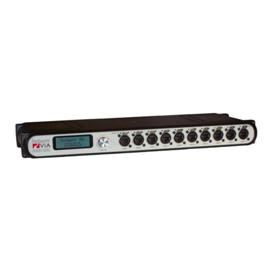
Page 4: Panel Layouts
Panel Layouts Front Panel – model 6740 shown Backlit LCD Screen Rotary Encoder Link\Act PoE Active Turn to highlight item on screen LED Indicator LED Indicator Push to select See manual for details LINK/ACT MANAGED GIGABIT ETHERNET SWITCH PORT 1 PORT 2 PORT 3 PORT 4... - Page 5 The Powercon plug may be connected to an AC power source with a voltage between 85 and 250VAC, either 50 or 60 Hz. The Speakon plug must only be connected to an auxiliary Power-over-Ethernet supply not to exceed 48 VDC. See below for more information on enabling and using PoE.
-
Page 6: Base Configuration Menu
Base Configuration Menu With the default screen shown on the LCD, press the encoder knob. The base configuration menu will be shown. Base Configuration Network Status Device Info/Status Turn the knob to scroll down the menu. The current menu item is highlighted in reverse video. -
Page 7: Network Setup
Network Setup Allows review of the IP address, subnet mask and default gateway used by the switch. To edit these properties, push the knob again. The first octet of the IP address will be highlighted. Turn the knob to change the value, and push to accept. -
Page 8: Device Info/Status
Device Info/Status Allows review of the following non-editable properties. Property Explanation Serial Number Factory-assigned, Pathway serial number MAC Address Factory-assigned media access control address Current operating firmware version. Firmware may Firmware Version be updated using Pathport Manager software Total Power-over-Ethernet being drawn by all PoE Used connected devices, in watts Total current Power-over-Ethernet budgeted to all... -
Page 9: Vlan Setup
VLAN Setup Allows review and editing of global VLAN properties used by the switch. By default, VLAN support is Disabled. Once VLAN support is Enabled, the following menu is shown. Property Explanation VLANs are active. If the status is reported as VLAN Support: Enabled Disabled, the items below will NOT be shown. - Page 10 VLAN Configuration and Setup The following options are available in firmware 3.6.1 and higher. A list of available VLANs, as defined in the menu above, will be shown. Select a VLAN to enter the configuration menu. Important: Although these values apply to the VLAN itself, and are independent of the overall settings of the switch, all values must be set on each switch in the network, for each VLAN in use on that switch.
-
Page 11: Ring Protect Setup
Ring Protect Setup This option will only be shown if VLAN support is enabled. Property Explanation Shows the current state of the switch. Press knob to change between: Ring Protect Mode: Disabled: Ring Protection feature is turned off Master: Only one switch may be set as the Master. Transit: All other switches must be set as Transit. -
Page 12: Port Status And Configuration Menu
Port Status and Configuration Menu Port Status may be reviewed by turning to rotary knob to reach the desired port. The LCD shows the following default information. <Port Name> Port x : <link speed> VLAN <x> The port’s soft label is shown on the top line. By default, the label is the port number. Below is shown the port number and the link status or speed. -
Page 13: Port Link Mode
Port Link Mode Allows review and editing of the port’s communication speed. Auto-negotiation allows the switch and the connected device to determine the fastest mutually supported connection speed. However, there are some situations where, due to poor cabling, interference or traffic congestion, ability to force the connection to a particular speed is desirable. -
Page 14: Port Vlan Configuration
Port VLAN Configuration Allows review and editing of the port’s VLAN properties. These properties are only shown if VLANs have been enabled. Plan the VLAN layout first. The creation of a map of the network, showing which devices and which ports to associate with a given VLAN, is strongly recommended prior to configuration. -
Page 15: Port Poe Setup/Status
Port PoE Setup/Status Allows review and management of power consumption used by devices running on Power-over-Ethernet (PoE) supplied by the VIA12. Except for Max Allocation, the PoE settings are not user-editable. The Maximum PoE Allocation allows you to set an upper limit to the power available to a connected device, such as a node. -
Page 16: Lldp Link Partner
LLDP Link Partner Link Layer Discovery Protocol (LLDP) is an industry-standard method for device announcement and reporting described in the IEEE 802.1AB standard. Any Ethernet- aware device may announce itself using LLDP, not just switches. Currently, the latest Pathport and VIA firmware enables this protocol. The information shown in the chart may be retrieved and shown on the VIA12’s LCD, for each Pathport LLDP-enabled device connected to the switch, on a port-by-port basis. -
Page 17: Appendix 1: Fiber Adapter Selection
Appendix 1: Fiber Adapter Selection The Pathway Connectivity VIA Gigabit Switch allows for the end user to provide a fiber adaptor. The adaptors are typically referred to as an SFP (Small Form Pluggable transceiver) or mini-GBIC (gigabit interface converter). Because of frequent catalog changes in the IT world, it is not possible to recommend part numbers from specific manufacturers. -
Page 18: Appendix 2: Virtual Local Area Network
Appendix 2: Virtual Local Area Network A VLAN (Virtual Local Area Network) is a group of ports on the switch (or switches) that are configured to pass traffic to one another, but not to ports on any other VLAN. When multiple VLANs are established, some ports on the switch may need to be configured specifically to pass all VLAN traffic, to ensure overall traffic is routed correctly. -
Page 19: Vlan Guidelines
VLAN Guidelines Plan the VLAN layout first. The creation of a map of the network, showing which devices to associate with which VLAN, is strongly recommended prior to configuration. Generally speaking, ports connected to end devices will be configured as Normal/Untagged and given a VLAN ID#. -
Page 20: Appendix 3: Ring Protection
Appendix 3: Ring Protection Ethernet wiring schemes are based on a ‘star’-wiring topology. Ring (or loop) data wiring – where the last device in a chain is wired back to the first device – is forbidden. Only one data path between any two devices is allowed. But star-wiring layouts are prone to single point failures. -
Page 21: Software Configuration Of Ring Protection
Ring Protect State: Complete indicates the ring is complete. Communication is relying on the primary port of the Master switch, and the overall network is secure. Ring Protect State: Failed indicates the ring is broken. Communication is relying on the secondary port of the Master switch, and the overall network is now vulnerable. The fault should be located and corrected.
Need help?
Do you have a question about the Pathport VIA12 and is the answer not in the manual?
Questions and answers