
Related Manuals for Pathway connectivity solutions Pathport VIA 6730


Summary of Contents for Pathway connectivity solutions Pathport VIA 6730
- Page 1 Pathport VIA Ethernet Switches User Guide and Manual Models running firmware 3.8.0 March 2016 © Acuity Brands Lighting Canada 1439 17 Ave SE Calgary AB T2G 1J9 403-243-8110 www.pathwayconnect.com...
-
Page 2: Table Of Contents
Table of Contents About Pathport VIA Ethernet Switches ................3 Installation Instructions ....................3 Panel Layouts ......................... 4 Front Panel – model 6730/6740 .................. 4 Main Display Messages ....................4 Rear Panel – model 6730 .................... 5 Rear Panel – model 6740 .................... 5 Rear Panel –... -
Page 3: About Pathport Via Ethernet Switches
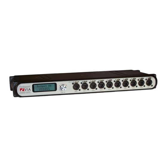
About Pathport VIA Ethernet Switches Pathport® VIA Gigabit Ethernet switches are designed for live entertainment Ethernet systems, including audio and DMX-over-Ethernet networks. This manual covers models 6730, 6740, 6741 and 6742 running firmware of 3.8.0 or higher. The VIA Ethernet Switch is intended specifically for signal routing between Pathport DMX-over-Ethernet nodes, or similar equipment, and Ethernet-aware lighting and audio control products, such as consoles and controllers and end equipment. -
Page 4: Panel Layouts
Panel Layouts Front Panel – model 6730/6740 Backlit LCD Screen Rotary Encoder Link\Act PoE Active Turn to highlight item on screen LED Indicator LED Indicator Push to select See manual for details LINK/ACT MANAGED GIGABIT ETHERNET SWITCH PORT 1 PORT 2 PORT 3 PORT 4 PORT 5... -
Page 5: Rear Panel - Model 6730
Rear Panel – model 6730 ATTENTION Mini-GBIC Risk of electric shock. 48VDC POE Disconnect power PRESENT before opening. Risque de decharge electrique. Debrancher LINK/ACT SD CARD le pouvoir avant d'ouvrier. ERROR 90-260VAC .75A 50/60 Hz 2.5mm Center Positive Mini-GBIC Port for Wide-Ranging IEC Input Fiber Optic Adaptor Auxiliary PoE Input... -
Page 6: Base Configuration
Base Configuration With the default screen shown on the LCD, press the encoder knob. The base configuration menu will be shown. Base Configuration Network Status Device Info/Status Turn the knob to scroll down the menu. The current menu item is highlighted in reverse video. -
Page 7: Network Setup
Network Setup Allows review and changes of the IP address, subnet mask and default gateway. These settings are the default values for VLAN 1, and will be used if VLANs are disabled. To edit these properties, push the knob again. IMPORTANT: If multicast filtering, or a DHCP server is required, DO NOT make changes to network settings here. -
Page 8: Device Info/Status
Device Info/Status Allows review of the following non-editable properties: Property Explanation Serial Number Factory-assigned, Pathway serial number MAC Address Factory-assigned media access control address Current operating firmware version. Firmware may be Firmware Version updated using software configuration tools OK: Ring is intact Init: Ring is initializing Ring Protect State Failed: Link between two ports has failed. -
Page 9: Advanced Settings
Advanced Settings Menu Item Menu Options Disabled (default) VLAN Support Enabled. Must be enabled to show VLAN Setup and Ring Protect feature Specifies lowest VLAN ID# available. VLAN Range Start: <x> Valid range: 1 to 4095. Default is 1. Specifies highest VLAN ID# available. VLAN Range End: <x>... -
Page 10: Vlan Support
Plan your VLAN layout before attempting configuration. The creation of a map of the network, showing which devices and which ports to associate with a given VLAN, is strongly recommended prior to configuration. EXTREMELY IMPORTANT NOTE: When configuring one or multiple VIA switches using Pathway’s software-based configuration tools, be certain all switches are set to the same Management VLAN ID#. -
Page 11: Vlan Config/Status: Network Settings
VLAN Config/Status: Network Settings Property Explanation Determines how IP settings will be obtained Disabled (default): No IP assigned. IP Mode Static: IP settings manually set by user. Dynamic: IP settings will be obtained from a DHCP server. Manually sets IP address (IPv4) IP Address Turn knob to set each octet. -
Page 12: Vlan Config/Status: Dhcp Server
VLAN Config/Status: DHCP Server VIA switches can automatically assign IP addresses to connected devices, using a DHCP (dynamic host configuration protocol) server. Important: Only one DHCP server may be active on any given VLAN at one time. Running multiple DHCP servers will cause network reliability problems. The DHCP-hosting VIA switch must first be set to a static IP address on the desired VLAN, prior to enabling the DHCP server. -
Page 13: Vlan Config/Status: Igmp And Multicast Groups
VLAN Config/Status: IGMP and Multicast Groups When using multicast data packets, such as streaming ACN (sACN), bandwidth efficiency may be improved by using IGMP (Internet group management protocol) to enable multicast filtering. Property Explanation Enable/disable IGMP snooping – allows the switch to IGMP Snooping correctly filter multi-cast traffic Enable/disable the IGMP querier –... -
Page 14: Ring Protect Setup
Ring Protect Setup This option will only be shown if VLAN support is enabled. Property Explanation Shows the current state of the switch. Press knob to change between: Ring Protect Mode: Disabled: Ring Protection feature is turned off Master: Only one switch may be set as the Master. Transit: All other switches must be set as Transit. -
Page 15: Alternate Art-Net Mapping
Alternate Art-Net Mapping This feature is used in conjunction with the ‘Broadcast Art-Net Trap-and-Convert to sACN’, which is set from the Port Configuration menu. This feature does not affect unicast Art-Net packets. The Art-Net protocol uses two hexadecimal numbers, a ‘subnet’ and a ‘universe’, to define its DMX universe numbering. -
Page 16: Utilities
Utilities Allows the switch to be rebooted or factory-defaulted from the front panel. The action must be confirmed before being applied. After confirmation, the rotary knob will be locked out, and about 15 to 20 seconds will pass before the LCD changes. Factory default disables and defaults all VLANs, but does not change the switch’s IP settings. -
Page 17: Port Status And Configuration Menu
Port Status and Configuration Menu Port Status may be reviewed by turning to rotary knob to reach the desired port. The LCD shows the following information. <Port Name> Port x : <link speed> VLAN <x> The port’s soft label is shown on the top line. By default, the label is the port number. Below is shown the port number and the link status or speed. -
Page 18: Vlan Type
VLAN Type VLANs must be enabled from the Advanced Settings menu for this option to be shown. Property Explanation Untagged (Normal): Only data belonging to the port’s specified VLAN ID# will be transmitted. Typically connected to end equipment. VLAN Tagged (Uplink): All traffic on all VLANs will be transmitted. Typically connected to another switch. -
Page 19: Art-Net To Sacn 'Trap-And-Convert
Art-Net to sACN ‘Trap-and-Convert’ This option is only shown for ports set as Untagged (Normal). When enabled, Art-Net data packets with broadcast address destinations are trapped and converted to E1.31 sACN multicast packets, as the packets enter the port of the switch. -
Page 20: Lldp Link Partner
Except for Maximum Allocation, the PoE settings are not user-editable. The Maximum PoE Allocation allows you to set an upper limit to the power available to a connected device, such as a node. Use Maximum Allocation to ensure critical devices will have power. -
Page 21: Port Link Mode
Port Link Mode Allows review and editing of the port’s communication speed. Auto-negotiation allows the switch and the connected device to determine the fastest mutually supported connection speed. However, there are some situations where, due to poor cabling, interference or traffic congestion, ability to force the connection to a particular speed is desirable. -
Page 22: Firmware Upgrades
Firmware Upgrades Firmware upgrades may only be done using the appropriate Pathway Connectivity software configuration tools, available from the Pathway Connectivity website: www.pathwayconnect.com. Software Configuration Tools With the release of the 3.8.0 firmware, Pathway is transitioning its published software configuration tools for the VIA switch products from Pathport Manager to the new VIA Manager. -
Page 23: Appendix 1: Sfp Fiber Adapter Selection
Appendix 1: SFP Fiber Adapter Selection The VIA Gigabit Switch models 6730 and 6740 allow the end user to provide a fiber adaptor. The adaptors are typically referred to as an SFP (Small Form Pluggable transceiver) or mini-GBIC (gigabit interface converter). Because of frequent catalog changes in the IT world, it is not possible to recommend part numbers from specific manufacturers. -
Page 24: Appendix 2: Virtual Local Area Network (Vlan)
Appendix 2: Virtual Local Area Network (VLAN) A VLAN (Virtual Local Area Network) is a group of ports on the switch (or switches) that are configured to pass traffic to one another, but not to ports on any other VLAN. When multiple VLANs are established, some ports on the switch may need to be configured specifically to pass all VLAN traffic, to ensure overall traffic is routed correctly. -
Page 25: Vlan Guidelines
VLAN Guidelines Plan the VLAN layout first. The creation of a map of the network, showing which devices to associate with which VLAN, is strongly recommended prior to configuration. Generally speaking, ports connected to end devices will be configured as Normal/Untagged and given a VLAN ID#. -
Page 26: Appendix 3: Ring Protection
Appendix 3: Ring Protection Ethernet wiring schemes are based on a ‘star’-wiring topology. Ring (or loop) data wiring – where the last device in a chain is wired back to the first device – is forbidden. Only one data path between any two devices is allowed. But star-wiring layouts are prone to single point failures. -
Page 27: Software Configuration Of Ring Protection
Ring Protect State: Complete indicates the ring is complete. Communication is relying on the primary port of the Master switch, and the overall network is secure. Ring Protect State: Failed indicates the ring is broken. Communication is relying on the secondary port of the Master switch, and the overall network is now vulnerable. The fault should be located and corrected. -
Page 28: Appendix 4: Qos Settings
Appendix 4: QoS Settings Quality of Service priorities are determined by the Differentiated Services Code Point (DSCP) field contained in each data packet header. DSCP values may range from 1 to 64, and are mapped to four egress (output) queues. The egress queues are, in turn, numbered from 1 (Best Effort) to 4 (Highest Priority).
Need help?
Do you have a question about the Pathport VIA 6730 and is the answer not in the manual?
Questions and answers