
Summary of Contents for Air Master AML 100
- Page 1 Ventilation in balance OPERATOR’S MANUAL AML 100 800; AMP 300 1200; CV 80 200; DV 1000...
-
Page 2: Safety Instructions
SAFETY INSTRUCTIONS This manual must be read before using the The manufacturer reserves the right to make Airmaster air handling unit. Compliance changes without notice. All values stated with the manual ensures correct use of this are nominal values and can be affected by product. -
Page 3: Table Of Contents
Table of Contents 1. Airlinq ................................5 2. Function Principle ............................5 3. Airlinq Viva (White Control Panel) .........................6 3.1. Control Elements ......................................6 3.2. Operation ..........................................6 3.2.1. Automatic Operating Lock ................................6 3.2.2. Child Lock......................................6 3.2.3. Start, Standby and Switch Off ..............................7 3.2.4. - Page 4 5. Control Functions ............................23 5.1. Timer-Controlled Ventilation ................................... 23 5.2. Night Time Cooling ....................................... 23 5.3. Holiday Mode ........................................23 5.4. Start and Stop Using External Contacts .............................. 23 5.5. Start and Stop Using a PIR sensor ................................. 23 5.6. Control Using a CO Sensor..................................
-
Page 5: Airlinq
Airlinq Function Principle Airmaster focuses not only on the air handling unit, but The diagram below shows the basic function of an Airmaster also on the control system software and operation. Airlinq air handling unit. is Airmaster’s own unique ventilation control system, which gives the user and service technician impressive overview and full control over the indoor climate, plus easy access to a host of functions, which ensure correct operation of... -
Page 6: Airlinq Viva (White Control Panel)
Airlinq Viva (White Control 3.2. Operation Panel) 3.2.1. Automatic Operating Lock 3.1. Control Elements The control panel is fitted with an automatic operating lock to prevent accidental air flow setting, e.g. during cleaning. The lock activates automatically after 30 seconds of no operation. -
Page 7: Start, Standby And Switch Off
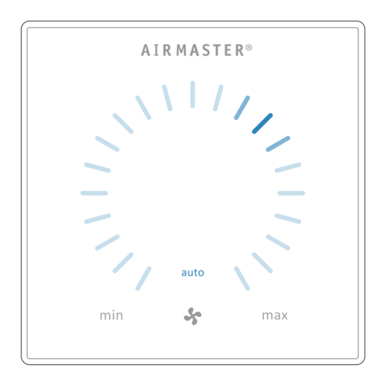
3.2.3. Start, Standby and Switch Off The current air flow and text “auto” are shown on the control panel with a blue light above the fan symbol. (See Airmaster’s air handling unit can be started and stopped 1st graphic below.) automatically or using the function button (pos. -
Page 8: Air Flow - Manuel Setting
3.2.4. Air Flow - Manuel Setting auto auto Press the current air flow. The automatic operating lock will cancel Drag your finger on the setting area when the air flow display is marked up to the current setting by blue clockwise to increase air flow or stripes. -
Page 9: Holiday Mode - Activation
3.2.5. Holiday Mode - Activation Warning and alarm displays (yellow and red): Holiday mode is used as basic ventilation when the room is unused for an extended period, e.g. holidays. auto auto In holiday mode, Airmaster will run the unit with min. air flow. The internal control system function “Low temperature”... - Page 10 Warning (yellow) Alarm (red) The air handling unit remains in operation in the event of a The air handling unit will stop to prevent damage in the warning, but can deviate from standard operation. event of an alarm. 1. Slow flash: 1.
-
Page 11: Airlinq Orbit (Black Control Panel)
Airlinq Orbit (Black Control “Selectable” Panel) “Selected”. 4.1. Control Elements “Increase” value. “Reduce” value. “Holiday mode” symbol shows for holiday mode instead of fan symbol (pos. 7.), see page 23. Padlock shows when operated with active automatic operating lock and active screen lock. "auto"... -
Page 12: Air Flow - Manuel Setting
4.2.2. Air Flow - Manuel Setting auto auto Cancel the operation lock or screen lock (if in use) and press the current Drag your finger on the setting area air flow until the air flow display is marked up to the current setting clockwise to increase air flow or with blue stripes. -
Page 13: Automatic Operation
4.2.3. Automatic Operation 4.2.4.1. Start and Standby Start or restart automatic operation. Press menu field “ AUTO”. >> The unit will start according to its programming if a start signal is active, or automatic operation will be reactivated after manual override. The current air flow will show with 5 blue stripes. -
Page 14: Off
4.2.4.2. Off 4.2.4.4. Status The Status menu is divided into 4 groups: Information, Flow, Filters and Operation. The menu points indicate the unit’s operational status. Press menu field “ STATUS” >> The sub-menu will activate. Press the required sub-menu. Information Total Operation time The unit’s operation hours since manufacture. - Page 15 Operation Operation Inlet Temp. Inlet temperature in°C. Started By Operation start signal Outside Temp. Vent. Outside temperature air - “External”, using external contacts handling unit in °C. and relays. Room Temperature Extraction temperature in°C. - “Airlinq”, manual start using a Exhaust Temp.
-
Page 16: Setup
4.2.4.5. Setup Timer-controlled ventilation lowest program: All operational parameters can be changed under the “ Air flow (Flow) 40%, Inlet temperature (Temp) 19 °C, SETUP” menu, according to local conditions. Start: 07:00, Stop: 17:00, Days: Monday to Friday (MO, TU, WE, TH, FR shown in white text), Saturday and Sunday are programmed inac- Timers tive (SA and SU shown in light grey text),... - Page 17 Adjust or add a program: Remove a program: After selecting the program to be adjusted, or use of the NIGHT TIME COOLING function button “Add” (see program view on previous page), 00:00 FLOW: 100% TEMP 16 ⁰ ‘Setting’ mode will start. 06:00 MO TU WE TH FR SA SU TIMER-CONTR.
-
Page 18: Date And Time
Date and Time This temperature setting does not generally need to be changed. Date and time are preprogrammed according to the calendar. Press High Temperature. Time changes automatically to summer and winter times. The summer/winter setting can be deactivated using the >>... -
Page 19: Startup Guide
Startup Guide Set code: The startup guide starts automatically when the unit is started for the first time. The guide can also be started manually subsequently (menu under “Setup”), e.g. to retro- install a CO sensor. The most important settings can be made using the startup guide. -
Page 20: Airlinq Bms
4.2.6. Airlinq BMS When using Airlinq BMS with up to 20 air handling units, the system is usually broken down into several groups (G) with at least one unit (ID) each, with all units in a group controlled uniformly. One of the units in a group will be programmed as the “Group Master”, which controls the entire group. -
Page 21: Select A Group/Unit
Control and setting >> The group selected will start according to the programming. Each group in the system is controlled and set in the same way as an individual unit. That means that all control options are available for all groups. The status menu and alarm view Start operation manual. -
Page 22: Warning And Alarm
4.3. Warning and Alarm Display of warnings and alarms with the unit’s ID number in an Airlinq BMS system. See page 20. ID 15 filter change required In the event of warnings and alarms, a triangle with an exclamation mark in its centre with an amber or red light (pos. -
Page 23: Control Functions
Control Functions 5.3. Holiday Mode Holiday mode is used as basic ventilation when the room 5.1. Timer-Controlled Ventilation is unused for an extended period, e.g. holidays. This function controls the Airmaster unit fully automatically according to a timer using an integrated clock. In holiday mode, Airlinq will run the unit with min. -
Page 24: Control Using A Co Sensor
5.6. Control Using a CO Sensor 2. Start, Stop and Air Flow Control A CO sensor is used to control the air handling unit inde- Air flow [%] pendent of the room’s CO level. The air flow can either be (1) controlled by the CO sensor, or let the unit’s complete operation be (2) controlled by the CO... -
Page 25: Boost
Internal Control Functions 5.7. Boost The boost function can adjust the airflow temporarily and Internal control functions run automatically, and influence is programmed to use some fixed control voltages for the air flow and inlet temperature. An internal control function supply fan and the exhaust fan respectively. -
Page 26: Virtual Preheat
6.3. Virtual Preheat means that the room temperature (RT) can be limited to an acceptable level. Virtual preheat ensures unit operation (along with the preheat process) at low outside temperatures for the CV80, Setpoint is set using the control panel menu point “High AML100, CV200, AML/AMP300 and DV1000 units. -
Page 27: Service And Maintenance
Service and Maintenance 7.3. Cleaning the Condensate System N.B. The condensate system must be cleaned minimum Service and maintenance are vital for problem-free opera- annually and must be controlled at every filter change. tion of an Airmaster unit and its equipment. The majority of servicing consists of cleaning and inspection of the condensate system and filter change. -
Page 28: Filter Change
7.4. Filter Change 7.4.2. Cooling Module Filter Change NB: When changing filters, the unit must be switched All filters in the air handling unit (inc. cooling module) are off (press function button for at least 2 seconds), monitored by the unit’s filter monitoring system. The filters disconnected from the mains and prevented from must be replaced when the monitoring system indicates a being switched on. -
Page 29: Filter Change For Cv80-200, Dv 1000, Aml100-800 And Amp300-800
7.4.3. Filter Change for CV80-200, DV 1000, Filter position: AML100-800 and AMP300-800 AML/AMP 300, 500, 800 H: Supply air filter (1) and These units are fitted with an exhaust air filter (M5 only) exhaust air filter (2) without retaining plate. and one or two fresh air filters (M5 or F7) unless fitted with a cooling module, in which case the air handling unit will only have one exhaust air filter. -
Page 30: Filter Change Amp900 And Amp1200
Retaining plate for fresh air filters (1) under exhaust air filter. 7.4.4. Filter Change AMP900 and AMP1200 NB: When changing filters, the unit must be switched off (press function button for at least 2 seconds), disconnected from the mains and prevented from being switched on. - Page 31 Filter position AMP900: Filter position AMP1200: 1. Supply air filter (1) (M5 or F7) behind the service cover Supply air filter (M5 or F7) is fitted behind the side panels on top of a 900 unit: on the motor section and is accessible from the lift and right sides.
-
Page 32: Filter List
7.5. Filter List Standard filters M5: Unit Location Measurements [mm] CV 80, AML 100 Supply/Extracted air 195 x 185 x 92 CV 200 Supply/Extracted air 242 x 220 x 92 AML/AMP 300 Supply air 280 x 220 x 47 AML/AMP 300... -
Page 33: Setting Inlet Opening
7.6. Setting Inlet Opening AML100, 300, 500 and 800, AMP300, 500 and 800 AMP900 The inlet opening louvres can be bent slightly using long- nosed pliers to adjust inlet direction. The inlet opening area can be adjusted and fixed at the top of the front cover using a cover plate. -
Page 34: Cooling Module - Safety Instructions
Fault Description 7.7. Cooling Module - Safety Instructions Control panel blank The cooling module is exempt from the directive for pressure 1. Unit switched off equipment (PED) according to article 1, part 3.6. Start unit manually. See page 7 or 13. 2. -
Page 35: Ec Declaration Of Conformity
EC Declaration of Conformity Manufacturer Airmaster A/S Industrivej 59 DK-9600 Aars Denmark herewith declare that the following air handling unit (series and type (serial numbers) Product CV80 and AML100 (3100001-3199999), CV200 (3200001-3299999), AML300 and AMP300 (0202042-0299999), AML500 and AMP500 (0300783-0399999), AML 800 and AMP800 (0900001-0999999), AMP900 (0500109-0599999), DV1000 (3300001-3399999) -
Page 36: Abbreviations
Abbreviations Percent °C Degrees Celsius Analogue input Airmaster L-series Airmaster P-series AQC L Airlinq Controller unit L-series AQC P Airlinq Controller unit P-series Building Management System Cooling module Condenser temperature Carbon dioxide CV series Electromagnetic compatibility Expanded Polypropylene Exhaust Temperature (Cooling Module) Exhaust Temperature Air Handling Unit Vaporiser temperature Filter class F7... -
Page 37: Quick Guide Airlinq Viva
Quick Guide Viva Cancel automatic operating lock. Press current air flow for at least 1 second. Set air flow. Press current air flow and drag with finger to desired Warning and Alarm. air flow. Flashes/constantly yellow for warn- ings and red for alarms. Holiday Mode Symbol. -
Page 38: Quick Guide Airlinq Orbit
Quick Guide Orbit Set air flow. Press current air flow and drag with finger to desired air flow. Press direct on the desired air flow. Warning and Alarm. Yellow for warnings and red for alarms. level symbol (shows with active CO sensor). -
Page 39: Notes
Notes... - Page 40 Airmaster Applied Solution Ltd. Phone +44 (0) 8448 099 993 PO Box 6102 Fax +44 (0) 1926 797 001 info@airmaster-as.co.uk Innovation Centre Gallows Hill Warwick www.airmaster-as.co.uk CV34 9PF United Kingdom...
Need help?
Do you have a question about the AML 100 and is the answer not in the manual?
Questions and answers