Lincoln Electric POWER WAVE S350 Operator's Manual
Lincoln electric welder user manual
Hide thumbs
Also See for POWER WAVE S350:
- Service manual (161 pages) ,
- Operator's manual (41 pages) ,
- Operator's manual (34 pages)
Table of Contents
Advertisement
RETURN TO MAIN MENU
IM10061-A
®
POWER WAVE S350
February, 2011
11694, 11782
For use with machines having Code Numbers:
Safety Depends on You
Lincoln arc welding and cutting
equipment is designed and built
with safety in mind. However,
your overall safety can be
increased by proper installation
... and thoughtful operation on
your part. DO NOT INSTALL,
OPERATE OR REPAIR THIS
EQUIPMENT WITHOUT READ-
ING THIS MANUAL AND THE
SAFETY PRECAUTIONS CON-
TAINED THROUGHOUT. And,
most importantly, think before
you act and be careful.
OPERATORʼS MANUAL
Copyright © Lincoln Global Inc.
• World's Leader in Welding and Cutting Products •
• Sales and Service through Subsidiaries and Distributors Worldwide •
Cleveland, Ohio 44117-1199 U.S.A. TEL: 216.481.8100 FAX: 216.486.1751 WEB SITE: www.lincolnelectric.com
Advertisement
Table of Contents

Related Manuals for Lincoln Electric POWER WAVE S350


Summary of Contents for Lincoln Electric POWER WAVE S350
- Page 1 RETURN TO MAIN MENU IM10061-A ® POWER WAVE S350 February, 2011 11694, 11782 For use with machines having Code Numbers: Safety Depends on You Lincoln arc welding and cutting equipment is designed and built with safety in mind. However, your overall safety can be increased by proper installation ...
-
Page 2: California Proposition 65 Warnings
351040, Miami, Florida 33135 or CSA Standard W117.2-1974. A Free copy of “Arc Welding Safety” booklet E205 is available from the Lincoln Electric Company, 22801 St. Clair Avenue, Cleveland, Ohio 44117-1199. BE SURE THAT ALL INSTALLATION, OPERATION, MAINTENANCE AND REPAIR PROCEDURES ARE PERFORMED ONLY BY QUALIFIED INDIVIDUALS. -
Page 3: Electric Shock Can Kill
ELECTRIC SHOCK can kill. 3.a. The electrode and work (or ground) circuits are electrically “hot” when the welder is on. Do not touch these “hot” parts with your bare skin or wet clothing. Wear dry, hole-free gloves to insulate hands. - Page 4 WELDING and CUTTING SPARKS can cause fire or explosion. 6.a. Remove fire hazards from the welding area. If this is not possible, cover them to prevent the welding sparks from starting a fire. Remember that welding materials from welding can easily go through small cracks and openings to adjacent areas.
- Page 5 PRÉCAUTIONS DE SÛRETÉ Pour votre propre protection lire et observer toutes les instructions et les précautions de sûreté specifiques qui parraissent dans ce manuel aussi bien que les précautions de sûreté générales suiv- antes: Sûreté Pour Soudage A LʼArc 1. Protegez-vous contre la secousse électrique: a.
- Page 6 Electric for advice or information about their use of our products. We respond to our customers based on the best information in our posses- sion at that time. Lincoln Electric is not in a position to warrant or guarantee such advice, and assumes no liability, with respect to such infor- mation or advice.
-
Page 7: Table Of Contents
Installation...Section A Technical Specifications ...A-1, A-2 Safety Precautions ...A-3 Location, Lifting ...A-3 Stacking ...A-3 Tilting...A-3 Input and Ground Connections ...A-3 Machine Grounding ...A-3 High Frequency Protection...A-3 Input Connection ...A-4 Input Fuse and Supply Wire ...A-4 Input Voltage Selection ...A-4 Power Cord Replacement ...A-4 Connection Diagram ...A-5, A-6 Recommended Work Cable Sizes ...A-7 Cable Inductance and its Effects on Welding...A-8... -
Page 8: Installation
TECHNICAL SPECIFICATIONS - POWER WAVE® S350 POWER SOURCE-INPUT VOLTAGE AND CURRENT Model Duty Cycle Input Voltage ± 10% 40% rating 208/230/400*460/575 K2823-3 50/60 Hz (*includes 380V to 413V) 100% rating INPUT VOLTAGE/PHASE/ 40%* FREQUENCY 300 Amps / 29 Volts 200-208/1/50/60 230/1/50/60 380-415/1/50/60 200-208/3/50/60... -
Page 9: Installation
PROCESS GMAW GMAW-Pulse FCAW GTAW-DC SMAW PHYSICAL DIMENSIONS MODEL HEIGHT K2823-3 20.40 in ( 518 mm) OPERATING TEMPERATURE RANGE Environmentally Hardened: -4°F to 104°F (-20C to 40C) IP23 155º(F) Insulation Class Weight does not include input cord. Thermal tests have been performed at ambient tem- perature. - Page 10 WAVE® S350. Installation should be made in accordance with the appropriate National Electrical Code, all local codes and the information in this manual. The frame of the welder must be grounded. A ground terminal marked with a ground symbol is located next to the input power connection block.
-
Page 11: Input Connection
Using input wire sizes, fuses or cir- cuit breakers smaller than recommended may result in "nuisance" shut-offs from welder inrush currents, even if the machine is not being used at high currents. INPUT VOLTAGE SELECTION The POWER WAVE®... -
Page 12: Connection Diagram
CONNECTION DIAGRAMS GTAW (TIG) WELDING A user interface is required for adjusting the TIG weld- ing settings. S-series user interface (K3001-1) can be installed into the power source (Figure A.3). Refer to the connection diagrams based on the user interface that is being used. - Page 13 REGULATOR FLOWMETER GAS HOSE PF10-M WIRE FEEDER INSTALLATION FIGURE A.5 MIG PROCESS ARCLINK CABLE K1543-[XX] TO POSITIVE (+) STUD POWER WAVE® S350 TO NEGATIVE (-) STUD WORK CLAMP WORK PIECE...
-
Page 14: Recommended Work Cable Sizes
RECOMMENDED WORK CABLE SIZES FOR ARC WELDING Connect the electrode and work cables between the appropriate output studs of the Power Wave S350 per the following guidelines: • Most welding applications run with the electrode being positive (+). For those applications, connect the electrode cable between the wire drive feed plate and the positive (+) output stud on the power source. -
Page 15: Cable Inductance And Its Effects On Welding
Sense Lead Kits (K940-xx) are available for this pur- pose. The Power Wave S350 has the ability to automatically sense when remote sense leads are connected. With this feature there are no requirements for setting-up the machine to use remote sense leads. - Page 16 "Voltage Sensing Considerations for Multiple Arc Systems." Negative Electrode Polarity The Power Wave S350 has the ability to automatically sense the polarity of the sense leads. With this fea- ture there are no set-up requirements for welding with negative electrode polarity.
-
Page 17: Voltage Sensing Considerations For Multiple Arc Systems
A-10 VOLTAGE SENSING CONSIDERATIONS FOR MULTIPLE ARC SYSTEMS Special care must be taken when more than one arc is welding simultaneously on a single part. Multiple arc applications do not necessarily dictate the use of remote work voltage sense leads, but they are strong- ly recommended. - Page 18 A-11 • For circumferential applications, connect all work leads on one side of the weld joint, and all of the work voltage sense leads on the opposite side, such that they are out of the current path. (See Figure 8.A) POWER SOURCE INSTALLATION...
-
Page 19: Control Cable Connections
INSTALLATION Connection Between Power Source and Ethernet Networks The Power Wave S350 is equipped with an IP67 rated ODVA compliant RJ-45 Ethernet connector, which is located on the rear panel. All external Ethernet equip- ment (cables, switches, etc.), as defined by the con- nection diagrams, must be supplied by the customer. -
Page 20: Operation
SAFETY PRECAUTIONS READ AND UNDERSTAND ENTIRE SECTION BEFORE OPERATING MACHINE. WARNING • ELECTRIC SHOCK CAN KILL. • Do not touch electrically live part or electrode with skin or wet clothing. • Insulate yourself from work and ground. • Always wear dry insulating gloves. •... -
Page 21: Product Description
Power Feed™ systems including future versions of ArcLink® feeders. RECOMMENDED PROCESSES The Power Wave S350 is a high speed, multi-process power source capable of regulating the current, volt- age, or power of the welding arc. With an output range... -
Page 22: Design Features
DESIGN FEATURES Loaded with Standard Features • Multiple process DC output range: 5 - 350 Amps • 200 – 600 VAC, 1/3 phase, 50-60Hz input power • New and Improved Line Voltage Compensation holds the output constant over wide input voltage fluctuations. -
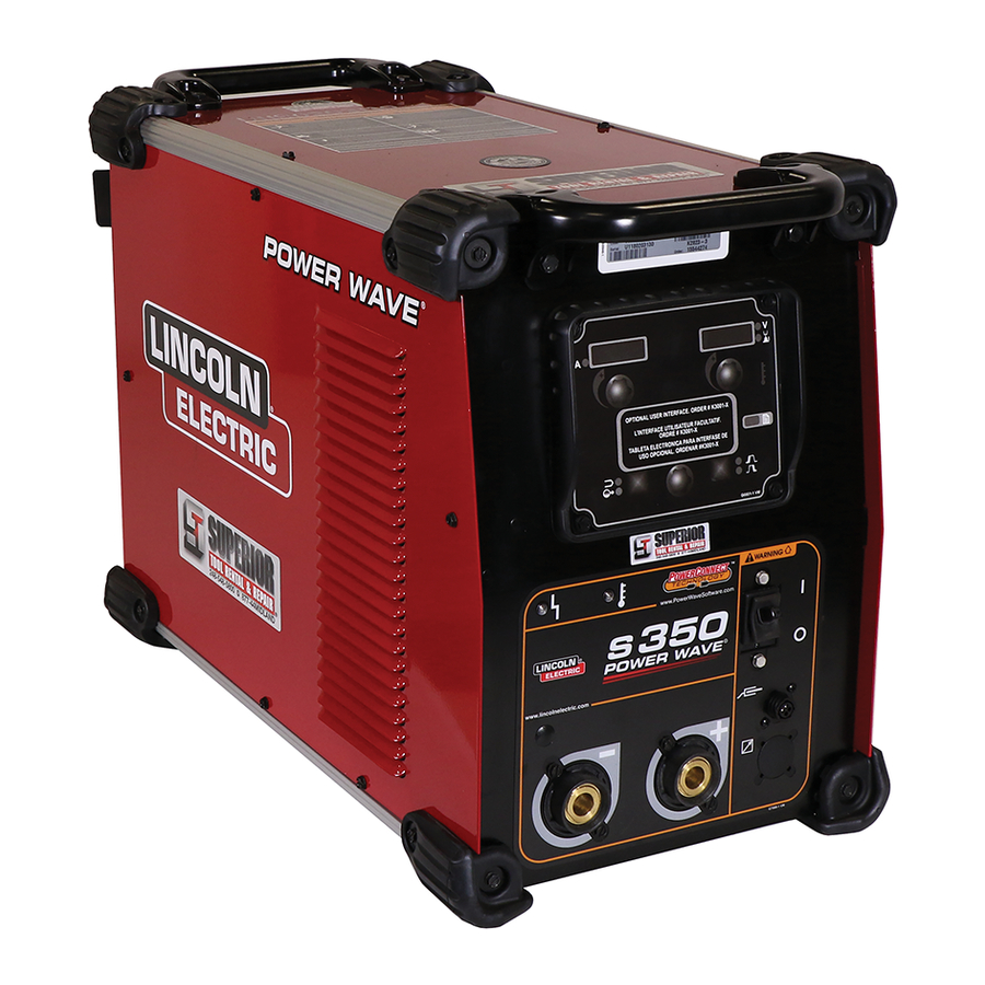
Page 23: Case Back Controls
CASE BACK CONTROLS (See Figure B.2 for Code 11694) 1. 115 VAC KIT (OPTIONAL) 2. ARCLINK CONNECTOR 3. CIRCUIT BREAKER 4. SYNC TANDEM/ STT CONNECTOR 5. DEVICENET KIT (OPTIONAL) 6. ETHERNET 7. RESERVED FOR FUTURE DEVELOPMENT 8. GAS SOLENOID KIT (OPTIONAL) FIGURE B.2 OPERATION CASE BACK CONTROLS... -
Page 24: Common Welding Procedures
Select the weld mode that best matches the desired welding process. The standard weld set shipped with the Power Wave S350 encompasses a wide range of common processes that will meet most needs. If a special weld mode is desired, contact the local Lincoln Electric sales representative. -
Page 25: Constant Voltage Welding
SMAW (STICK) WELDING The welding current and Arc Force settings can be set through a Power Feed 10M or Power Feed 25M wire feeder. Alternatively an optional Stick / TIG UI can be installed into the power source to control these set- tings locally. - Page 26 OPERATION Most pulse welding programs are synergic. As the wire feed speed is adjusted, the Power Wave® S350 will automatically recalculate the waveform parame- ters to maintain similar arc properties. The Power Wave® S350 utilizes “adaptive control” to compensate for changes in the electrical stick-out while welding.
-
Page 27: Kits, Options And Accessories
Order K3001-1 115 VAC Auxiliary Power Kit Mounts inside the back of the Power Wave S350. Adds 115 VAC / 60 Hz auxiliary power capability to the Power Wave S350 ( only compatible with the K2823-1 power source) -
Page 28: Stick Options
STICK OPTIONS ACCESSORY KIT - 150 Amp For stick welding. Includes 20 ft. (6.1m) #6 electrode cable with lug, 15 ft. (4.6m) #6 work cable with lugs, headshield, filter plate, work clamp, electrode holder and sample pack of mild steel electrode. For use with K2946-1. ORDER K875 ACCESSORY KIT - 400 AMP For stick welding. -
Page 29: Maintenance
SAFETY PRECAUTIONS ELECTRIC SHOCK can kill. • Turn the input power to the welding power • Only qualified personnel should install, use or ------------------------------------------------------------------------ ROUTINE MAINTENANCE Routine maintenance consists of periodically blowing out the machine, using a low-pressure air stream, to remove accumulated dust and dirt from the intake and outlet louvers, and the cooling channels in the machine. -
Page 30: Troubleshooting
HOW TO USE TROUBLESHOOTING GUIDE Service and Repair should only be performed by Lincoln Electric Factory Trained Personnel. Unauthorized repairs performed on this equipment may result in danger to the technician and machine operator and will invalidate your factory warranty. For your safety and to avoid Electrical Shock, please observe all safety notes and precautions detailed throughout this manual. -
Page 31: Using The Status Led To Troubleshoot System Problems
USING THE STATUS LED TO TROUBLESHOOT SYSTEM PROBLEMS Not all of the Power Wave S350 errors will be displayed on the user interface (if it is installed). There are two status lights that display error codes. If a problem occurs it is important to note the condition of the status lights. -
Page 32: Error Codes
Observe all Safety Guidelines detailed throughout this manual ERROR CODES FOR THE POWER WAVE® S350 The following is a partial list of possible error codes for the POWER WAVE® S350. For a complete listing consult the Service Manual for this machine. Error Code # Thermal error 54 Secondary (Output) over current error... - Page 33 Observe all Safety Guidelines detailed throughout this manual Error Code # Peak input current limit Under-voltage lockout Thermal Fault Pre-charge timeout Transformer primary over current Other If for any reason you do not understand the test procedures or are unable to perform the tests/repairs safely, contact your Local Lincoln Authorized Field Service Facility for technical troubleshooting assistance before you proceed.
- Page 34 2. Reduce output current, duty cycle, or both. 3. Contact your local authorized Lincoln Electric Field Service facility for technical assistance. 1. Make sure input supply discon- nect has been turned ON. Check input fuses. Make certain that the Power Switch (SW1) on the power source is in the “ON”...
- Page 35 Observe all Safety Guidelines detailed throughout this manual PROBLEMS (SYMPTOMS) Thermal LED is ON Thermal LED is ON “Real Time Clock” no longer func- tioning General degradation of weld perfor- mance If for any reason you do not understand the test procedures or are unable to perform the tests/repairs safely, contact your Local Lincoln Authorized Field Service Facility for technical troubleshooting assistance before you proceed.
- Page 36 Observe all Safety Guidelines detailed throughout this manual PROBLEMS (SYMPTOMS) Weld and Arc Quality Problems (Continued) Wire burns back to tip at the end of the weld. Machine output shuts down during a weld. Machine wonʼt produce full output. Excessively long and erratic arc. If for any reason you do not understand the test procedures or are unable to perform the tests/repairs safely, contact your Local Lincoln Authorized Field Service Facility for technical troubleshooting assistance before you proceed.
- Page 37 Observe all Safety Guidelines detailed throughout this manual PROBLEMS (SYMPTOMS) Cannot Connect Connection Drops while welding If for any reason you do not understand the test procedures or are unable to perform the tests/repairs safely, contact your Local Lincoln Authorized Field Service Facility for technical troubleshooting assistance before you proceed. TROUBLESHOOTING POSSIBLE CAUSE...
- Page 38 DIAGRAMS xxxxxxx xxxxxxx POWER WAVE® S350...
-
Page 39: Dimension Print
DIMENSION PRINT 27.43 22.25 13.91 18.81 6.00 18.36 POWER WAVE® S350... - Page 40 WARNING Spanish AVISO DE PRECAUCION French ATTENTION German WARNUNG Portuguese ATENÇÃO Japanese Chinese Korean Arabic READ AND UNDERSTAND THE MANUFACTURER’S INSTRUCTION FOR THIS EQUIPMENT AND THE CONSUMABLES TO BE USED AND FOLLOW YOUR EMPLOYER’S SAFETY PRACTICES. SE RECOMIENDA LEER Y ENTENDER LAS INSTRUCCIONES DEL FABRICANTE PARA EL USO DE ESTE EQUIPO Y LOS CONSUMIBLES QUE VA A UTILIZAR, SIGA LAS MEDIDAS DE SEGURIDAD DE SU SUPERVISOR.
- Page 41 Keep your head out of fumes. Turn power off before servicing. Use ventilation or exhaust to remove fumes from breathing zone. Los humos fuera de la zona de res- Desconectar el cable de ali- piración. mentación de poder de la máquina Mantenga la cabeza fuera de los antes de iniciar cualquier servicio.
- Page 42 • World's Leader in Welding and Cutting Products • • Sales and Service through Subsidiaries and Distributors Worldwide • Cleveland, Ohio 44117-1199 U.S.A. TEL: 216.481.8100 FAX: 216.486.1751 WEB SITE: www.lincolnelectric.com...
Need help?
Do you have a question about the POWER WAVE S350 and is the answer not in the manual?
Questions and answers