Lincoln Electric SAE-400 Operator's Manual
Hide thumbs
Also See for SAE-400:
- Operator's manual (60 pages) ,
- Technical specifications (6 pages) ,
- Specification sheet (168 pages)
Table of Contents
Advertisement
Quick Links
Operator's Manual
SAE-400
Register your machine:
www.lincolnelectric.com/register
Authorized Service and Distributor Locator:
www.lincolnelectric.com/locator
Save for future reference
Date Purchased
Code: (ex: 10859)
Serial: (ex: U1060512345)
IM10027-C
| Issue D ate Aug-15
© Lincoln Global, Inc. All Rights Reserved.
®
For use with machines having Code Numbers:
11605, 11807, 11966, 12311
Advertisement
Table of Contents
Troubleshooting

Related Manuals for Lincoln Electric SAE-400


Summary of Contents for Lincoln Electric SAE-400
- Page 1 Operator’s Manual ® SAE-400 For use with machines having Code Numbers: 11605, 11807, 11966, 12311 Register your machine: www.lincolnelectric.com/register Authorized Service and Distributor Locator: www.lincolnelectric.com/locator Save for future reference Date Purchased Code: (ex: 10859) Serial: (ex: U1060512345) IM10027-C | Issue D ate Aug-15...
- Page 2 THANK YOU FOR SELECTING A QUALITY PRODUCT BY KEEP YOUR HEAD OUT OF THE FUMES. DON’T get too close to the arc. LINCOLN ELEC TRIC. Use corrective lenses if necessary to stay a reasonable distance away from the arc. READ and obey the Material PLEASE EXAMINE CARTON AND EQUIPMENT FOR Safety Data Sheet (MSDS) and DAMAGE IMMEDIATELY...
- Page 3 SAFETY SECTION A: 1.d. Keep all equipment safety guards, covers and devices in position and in good repair.Keep hands, hair, clothing and tools away from WARNINGS V-belts, gears, fans and all other moving parts when starting, operating or repairing equipment. CALIFORNIA PROPOSITION 65 WARNINGS Diesel Engines 1.e.
- Page 4 SAFETY ELECTRIC SHOCK ARC RAYS CAN BURN. CAN KILL. 3.a. The electrode and work (or ground) circuits are 4.a. Use a shield with the proper filter and cover plates to protect your electrically “hot” when the welder is on. Do eyes from sparks and the rays of the arc when welding or not touch these “hot”...
- Page 5 SAFETY WELDING AND CUTTING CYLINDER MAY EXPLODE IF SPARKS CAN CAUSE DAMAGED. FIRE OR EXPLOSION. 7.a. Use only compressed gas cylinders containing the correct shielding gas for the process used 6.a. Remove fire hazards from the welding area. If and properly operating regulators designed for this is not possible, cover them to prevent the welding sparks the gas and pressure used.
- Page 6 SAE-400 TABLE OF CONTENTS ®...
- Page 7 INSTALLATION SAE-400 ® TECHNICAL SPECIFICATIONS SAE-400® (K1278-14) INPUT - DIESEL ENGINE STARTING MAKE/MODEL DESCRIPTION SPEED (RPM) DISPLACEMENT SYSTEM CAPACITIES FUEL: PERKINS 22.5 GAL. 269 CU. IN (4.4 L) 1104A-44 DIESEL HIGH IDLE 1800 12VDC 4 CYLINDER OIL: BORE X STROKE...
-
Page 8: Safety Precautions
INSTALLATION SAE-400 ® SAFETY PRECAUTIONS STACKING These machines cannot be stacked. Read this entire installation section before you start installation. Do not attempt to use this equipment until you have thoroughly ANGLE OF OPERATION read all operating and maintenance manuals supplied with your To achieve optimum engine performance the machine should be machine. - Page 9 The recommended trailers for use with this equipment for in-plant the engine Operator’s Manual for specific oil recommendations and yard towing by a vehicle(1) are Lincoln Electric K2641-2 and and break-in information. The oil change interval is dependent on K2637-2. The K2637-2 is also designed to be used at highway the quality of the oil and the operating environment.
- Page 10 ENGINE BREAK-IN PERIOD • CONNECTING A BATTERY CHARGER — remove Lincoln Electric selects high quality, heavy-duty industrial engines battery from welder by disconnecting negative cable for the portable welding machines we offer. While it is normal to first, then positive cable and battery clamp. When see a small amount of crankcase oil consumption during initial reinstalling, connect negative cable last.
- Page 11 INSTALLATION SAE-400 ® SPARK ARRESTER WELDING OUTPUT CABLES With the engine off, connect the electrode and work cables to the WARNING studs provided. These connections should be checked periodically and tightened if necessary. • Spark Arrester and Muffler may be hot! Listed in Table A.1 are copper cable sizes recommended for the...
-
Page 12: Safety Instructions
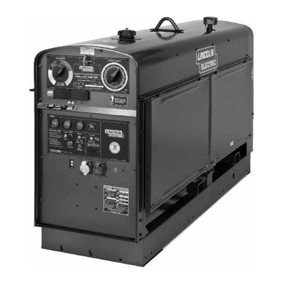
Wear eye, ear, and body protection. GENERAL DESCRIPTION The SAE-400 ® is a diesel engine driven welding power source. • Only qualified personnel should install, use or The machine uses a DC generator for DC stick electrode welding service this equipment. - Page 13 10 to 14 seconds after welding or use of auxiliary power AUXILIARY POWER stops. Includes high idle switch. The SAE-400® provides 3 KW of 115/230 VAC output for • Gauges for engine oil pressure, coolant temperature and auxiliary power and emergency standby power.
- Page 14 SAE-400 OPERATION ® ENGINE TEMPERATURE GAUGE CURRENT CONTROL Displays the coolant temperature in the engine block. ENGINE Oil Pressure Gauge CAUTION Displays the oil pressure to the engine. When the engine starts running, watch for the oil pressure to build up. If no pressure Do not adjust the “Current Control”...
- Page 15 ® AUxILIARY POWER CONTROLS RESIDUAL CURRENT DEVICE The SAE-400® is configured to allow for the addition of a 115 VAC Receptacle Residual Current Device (RCD) to protect the 240V Single Phase One 20 amp, 115VAC (5-20R) NEMA duplex receptacle provides Receptacle.
-
Page 16: Cold Weather Starting
SAE-400 OPERATION ® ENGINE OPERATION STARTING INSTRUCTIONS Be sure all Pre-Operation Maintenance has been performed. (See WARNING INSTALLATION section of this manual). 1. Turn the “IDLER” switch to “HIGH”. Do not attempt to use this equipment until you have 2. Turn the “IGNITION” switch to “ON”. - Page 17 SAE-400 OPERATION ® TYPICAL FUEL CONSUMPTION The typical fuel consumption of the SAE-400® for various operating scenarios is shown below: PERKINS 1104A-44 LOW IDLE - NO LOAD .26 GAL./ HR.(.97 L./HR.) 1100 RPM HIGH IDLE - NO LOAD .68 GAL./HR.(2.56 L./HR.)
- Page 18 Pipe Thawing with an arc welder can cause fire, explosion, damage to electric wiring or to the arc welder if done improperly. The use of an arc welder for pipe thawing is not approved by the CSA, nor is it recommended or supported by Lincoln Electric.
- Page 19 SAE-400 MAINTENANCE ® MAINTENANCE PERIODIC MAINTENANCE 1. Blow out the welder and controls with an air hose at least WARNING once every two months. In particularly dirty locations, this cleaning may be necessary once a week. Use low pressure air to avoid driving dirt into the insulation.
- Page 20 MAINTENANCE ® Commutator and Brush Maintenance Cooling System The SAE-400® is equipped with a pressure radiator. Keep the WARNING radiator cap tight to prevent loss of coolant. Clean and flush the cooling system periodically to prevent clogging the passage and overheating the engine.
- Page 21 8. Open the air vent valve on the front of the filter header until fuel emerges free of air bubbles and then close the air vent valve. SAE-400® with integral spark arresting mufflers: Note: Consult your engine operation manual for information Service spark arrester every 250 hours.
-
Page 22: Troubleshooting
TROUBLESHOOTING TROUBLESHOOTING WARNING Service and Repair should only be performed by Lincoln Electric Factory Trained Personnel. Unauthorized repairs performed on this equipment may result in danger to the technician and machine operator and will invalidate your factory warranty. For your safety and to avoid Electrical Shock, please observe all safety notes and precautions detailed throughout this manual. - Page 23 SAE-400® TROUBLESHOOTING Observe all Safety Guidelines detailed throughout this manual PROBLEM POSSIBLE CAUSE RECOMMENDED COURSE OF ACTION Machine fails to hold the 1. Rough or dirty commutator. 1. True and clean commutator.justment have been “heat” constantly. checked and the problem persists, Contact your local Lincoln Authorized Field Service Facility.
- Page 24 SAE-400 TROUBLESHOOTING ® Observe all Safety Guidelines detailed throughout this manual PROBLEM POSSIBLE CAUSE RECOMMENDED COURSE OF ACTION Welder runs but fails to 1. Generator or exciter brushes may be loose 1. Be sure that all brushes bear on the commutator and generate current.
- Page 25 P-909-B.2 Miscellaneous Items P-909-C Final Assembly P-909-D Engine Assembly P-909-E Generator-Alternator Assembly P-909-F Lower Control Panel Assembly P-909-G Control Panel Assembly P-909-H Left Gas Tank Rail & Output Panel P-909-J Remote Control P-909-K Generator Brush Holder SAE-400 (Perkins) - 12311...
- Page 26 DECAL-WARNING 9SM16679 DECAL-WARNING 9ST13086-26 DECAL 9ST13260-4 DECAL-EARTH GROUND CONN 9ST11030 DECAL-DOOROPEN-CLOSE 9SM16197 DECAL-WARNING 9SM17238 INSTRUCTION TAG 9SS25896 DECAL-WARNING 9SS26005 SERVICE DECAL 9SM25498 Wiring Diagram 9SM21436 CARBON MONOXIDE WARNING DECAL 9SL16028 NAMEPLATE-UPPER CONTROL PANEL 9ST14659-2 FASTENER BUTTON SAE-400 (Perkins) - 12311...
- Page 27 Miscellaneous Items PART NUMBER DESCRIPTION 9SS29243 DECAL ENGINE CIRCUIT BREAKER SAE-400 (Perkins) - 12311...
- Page 28 Miscellaneous Items No Image SAE-400 (Perkins) - 12311...
- Page 29 9ST9860-4 LOCKWASHER 9SS9225-28 THREAD FORMING SCREW 9SM8889-3 LIFT BALE ASBLY 9ST8833-24 HEX HD CAP SCREW 9SE106A-15 LOCKWASHER 9SCF000027 1/2-13HN 9SS12934-2 COVER SEAL 9SM12005-6 SIDE RAIL 9SCF000030 1/2-13X1.25HHCS 9SS9262-1 PLAIN WASHER 9SE106A-15 LOCKWASHER 9SCF000027 1/2-13HN 9SCF000030 1/2-13X1.25HHCS SAE-400 (Perkins) - 12311...
- Page 30 PLAIN WASHER 9SE106A-2 LOCKWASHER 9SCF000017 1/4-20HN 9SM20542-1 FAN GUARD (PUMP SIDE) 9SM20811-1 FAN GUARD (ALTERNATOR SIDE) 9SM20897-1 FAN GUARD TOP 9SM15045-37 ACOUSTICAL FOAM 9SS8025-12 SELF TAPPING SCREW 9SS8025-79 SELF TAPPING SCREW 9ST14731-13 METRIC HD SCREW-M10 X 1.5 SAE-400 (Perkins) - 12311...
- Page 31 DOOR HOOK ASBLY 9ST10878 WASHER 9SS8025-92 SELF TAPPING SCREW 9SS10656-2 DOOR HOOK ASBLY 9ST10878 WASHER 9SS8025-92 SELF TAPPING SCREW 9SS25474 DOOR RESTRAINT ASBLY 9SS24739-2 MISC STAINLESS STEEL SCREW 9SS9262-174 PLAIN WASHER (SS) 9SE106A-22 WASHER #10 LOCK (SS) SAE-400 (Perkins) - 12311...
- Page 32 Final Assembly PART NUMBER DESCRIPTION 9SCF000393 #10-24SS-HN 9SS20290 SPRING CLIP 9SS24739-29 #10-24X.38RHS-FULL-SS 9SS9262-174 PLAIN WASHER (SS) 9SE106A-22 WASHER #10 LOCK (SS) 9SCF000393 #10-24SS-HN 9SM18959-2 BREAKER & RECEPTACLE GUARD ASBLY 9SS9225-68 THREAD FORMING SCREW (CUTTING) SAE-400 (Perkins) - 12311...
- Page 33 Final Assembly P-909-C.jpg SAE-400 (Perkins) - 12311...
- Page 34 IDLER SOLENOID ASBLY 9SS20140-8 SOLENOID ASSEMBLY 9SM20527-1 IDLER SOLENOID BRACKET 9ST11525-5 SPEED NUT1/4-20 9SS9225-66 SELF TAPPING SCREW 9SE106A-2 LOCKWASHER 9SS22070 IN-LINE SWIVEL 9SS26643 IDLER LINKAGE 9SCF000060 1/4-28HJN 9SS22232 ROD END SWIVEL 9SCF000015 1/4-20X1.00HHCS 9SE106A-2 LOCKWASHER 9SCF000017 1/4-20HN SAE-400 (Perkins) - 12311...
- Page 35 9ST14731-4 METRIC HEX HD SCREW-M8 X1.25 9SS9262-121 PLAIN WASHER 9SE106A-3 LOCKWASHER 9SS25162 SWITCH WATER 9SS25992 OIL FILTER SPACER 9ST14731-3 METRIC HEX HD SCREW-M8 X1.25 9SS26001 GASKET 9SE106A-24 WASHER 5/16 LOCK (SS) 9SS26426 AMP TO LUCAR ADAPTER SAE-400 (Perkins) - 12311...
- Page 36 Engine Assembly P-909-D.jpg SAE-400 (Perkins) - 12311...
- Page 37 BRUSH ASBLY RETAINER 9SM19896 BRUSH HOLDER BRACKET (SS) 9SCF000014 1/4-20X.75HHCS 9SS9262-23 PLAIN WASHER 9SE106A-2 LOCKWASHER 9SCF000017 1/4-20HN 9SM13690-1 TOP EXCITER COVER WELDEDASBLY 9ST9860-6 LOCKWASHER 9SS9225-8 THREAD FORMING SCREW (ROLLING) 9ST6225-1 EXCITER LOCK NUT 9ST7090-1 EXCITER NUT WASHER SAE-400 (Perkins) - 12311...
- Page 38 Generator-Alternator Assembly PART NUMBER DESCRIPTION 9ST14337 ARMATURE SLEEVE COLLAR 9SM13686 BOTTOM EXCITER COVER 9ST9860-6 LOCKWASHER 9SS9225-8 THREAD FORMING SCREW (ROLLING) 9SCF000067 3/8-16HN SAE-400 (Perkins) - 12311...
- Page 39 Generator-Alternator Assembly P-909-E.jpg SAE-400 (Perkins) - 12311...
- Page 40 9ST9695-1 LOCKWASHER 9SCF000010 #10-24HN 9SL12400-3V1 IDLER/ENGINE SHUTDOWN PC BD ASBLY 9SCF000149 #10-24X1.25RHS 9SS9262-27 PLAIN WASHER 9SE106A-1 LOCKWASHER 9SCF000010 #10-24HN 9SS18250-397 PLUG & LEAD ASBLY 9SG8186 Harness 9ST14659-1 FASTENER BUTTON 9SM20152-2 RECEPTACLE-115V 9SS9225-63 THREAD FORMING SCREW (CUTTING) SAE-400 (Perkins) - 12311...
- Page 41 9SS9225-63 THREAD FORMING SCREW (CUTTING) 9SS28004-2 COVER PLATE 9SS9225-63 THREAD FORMING SCREW (CUTTING) 9SM22328 RECEPTACLE GUARD 9SS9225-63 THREAD FORMING SCREW (CUTTING) 9SS26843-1 GFCI REWORK 9SS28464 GFCI COVER 9SL13286 GFCI HOUSING 9SS27167 MOUNTING BRACKET 9SS24738-3 THERMOPLASTIC SCREW SAE-400 (Perkins) - 12311...
- Page 42 Lower Control Panel Assembly P-909-F.jpg SAE-400 (Perkins) - 12311...
- Page 43 9SS9262-41 PLAIN WASHER 9ST8236 SPRING 9SL2036-B REACTOR 9SS9225-8 THREAD FORMING SCREW (ROLLING) 9ST8280 RESISTOR-WIREWOUND 9SCF000045 #10-24X5.00RHS 9SE106A-1 LOCKWASHER 9SCF000010 #10-24HN 9ST13339 CAUTION DECAL 9ST13637 SILICON BRIDGE ASBLY 9SCF000059 #8-32X.875RHS 9SS9262-3 PLAIN WASHER 9ST4291-A LOCKWASHER 9SCF000042 #8-32HN SAE-400 (Perkins) - 12311...
- Page 44 SELF TAPPING SCREW 9ST12287-22 CIRCUIT BREAKER-15A 9ST12287-31 CIRCUIT BREAKER-20A250VAC32VDC 9SS22061-1 CIRCUIT BREAKER BOOT 9SM20585-3 CIRCUIT BREAKER 2 POLE 9SS24911-2 COVER CIRCUIT BREAKER 2 POLE 9ST10082-30 SEMS SCREW 9ST4291-A LOCKWASHER 9SS14165-463 RECEPTACLE & LEAD ASBLY 9SS26606 DECAL SPARK ARRESTER SAE-400 (Perkins) - 12311...
- Page 45 Control Panel Assembly P-909-G.jpg SAE-400 (Perkins) - 12311...
- Page 46 RAIL & OUTPUT PANEL ASBLY 9ST14166-9 OUTPUT TERMINAL KIT 9SCF000030 1/2-13X1.25HHCS 9SE106A-5 LOCKWASHER 9SCF000027 1/2-13HN 9SS9262-1 PLAIN WASHER 9SCF000020 1/2-13X.75HHCS 9SCF000344 HEX HD SCREW 9SS9262-1 PLAIN WASHER 9SE106A-15 LOCKWASHER 9ST3960 FLANGE NUT 9SS25371 DECALELECTRODE 9SS25372 DECALTO WORK SAE-400 (Perkins) - 12311...
- Page 47 Left Gas Tank Rail & Output Panel P-909-H.jpg SAE-400 (Perkins) - 12311...
-
Page 48: Remote Control
BOX CONNECTOR 9SS21007 CABLE ASBLY 9SCF000102 #8-32X.50BR-RHS 9SCF000103 #8-32BR-HN 9SM17285 RESISTOR BANK ASBLY 9SS21009 RESISTOR MTG BRKT 9SS10404-22 RESISTOR-WIREWOUND 9SCF000045 #10-24X5.00RHS 9ST4479-A INSULATING WASHER 9SE106A-1 LOCKWASHER 9SCF000010 #10-24HN 9SCF000102 #8-32X.50BR-RHS 9SCF000103 #8-32BR-HN 9SS8025-92 SELF TAPPING SCREW SAE-400 (Perkins) - 12311... - Page 49 Remote Control P-909-J.jpg SAE-400 (Perkins) - 12311...
- Page 50 INSULATING WASHER 9SS13721-2 BRUSH HOLDER STUD INSULATION 9ST9020 PLAIN WASHER 9SM6963-6 BRUSH HOLDER STUD 9SM6304-2B RETAINER 9SE106A-3 LOCKWASHER 9SCF000040 5/16-18X.75HHCS 9ST8495 BRUSH HOLDER SPRING & CLIP ASBLY 9ST8241 Brush Holder Spring Clip 9SE106A-3 LOCKWASHER 9SCF000040 5/16-18X.75HHCS SAE-400 (Perkins) - 12311...
- Page 51 Generator Brush Holder P-909-K.jpg SAE-400 (Perkins) - 12311...
- Page 52 SAE-400 DIAGRAMS ®...
- Page 53 SAE-400 DIAGRAMS ®...
- Page 54 SAE-400 DIAGRAMS ® WHITE > >...
- Page 55 SAE-400 DIAGRAMS ®...
- Page 56 SAE-400 DIAGRAMS ® INSTRUCTIONS FOR INSTALLING A 2-POLE RESIDUAL CURRENT DEVICE TO PROTECT THE 230V SINGLE PHASE RECEPTACLE S. WARNING MOVING PARTS can injure ELECTRIC SHOCK can kill Do not operate with panels open. Keep guards in place. Disconnect NEGATIVE (-) BATTERY LEAD(S) Keep away from moving parts.
- Page 57 SAE-400 DIAGRAMS ® FIGURE 1 Lower Control Panel Cover Plate 230V Euro Receptacle FRONT PANEL RED 7A FIGURE 2 RED 6A 2-POLE RCD RCD Mounting Strap RCD SEALING BOOT BLACK 6C Sleeving BLACK 7C FIGURE 3 Sleeving (Route out of lower corner of RCD cover box to upper control panel.)
- Page 58 WARNING Do not touch electrically live parts or Keep flammable materials away. Wear eye, ear and body protection. electrode with skin or wet clothing. Insulate yourself from work and AVISO DE ground. Spanish PRECAUCION No toque las partes o los electrodos Mantenga el material combustible Protéjase los ojos, los oídos y el bajo carga con la piel o ropa moja-...
- Page 59 WARNING Keep your head out of fumes. Turn power off before servicing. Do not operate with panel open or Use ventilation or exhaust to guards off. remove fumes from breathing zone. AVISO DE Spanish PRECAUCION Los humos fuera de la zona de res- Desconectar el cable de ali- No operar con panel abierto o piración.
- Page 60 We respond to our customers based on the best information in our possession at that time. Lincoln Electric is not in a position to warrant or guarantee such advice, and assumes no liability, with respect to such information or advice.
Need help?
Do you have a question about the SAE-400 and is the answer not in the manual?
Questions and answers