Table of Contents
Advertisement
THANK YOU!
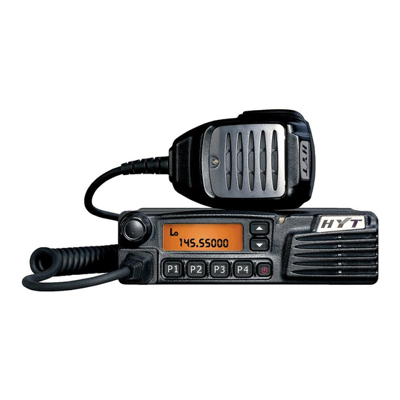
Thank you for your purchase of HYT mobile radio TM-610. We believe this easy-to-use
radio will provide you with dependable and reliable communications at peak efficiency.
Please read this manual carefully before use. The information presented herein will help
you to derive maximum performance from your radio.
MODELS COVERED IN THIS MANUAL
TM-610 VHF Mobile Radio
TM-610 UHF Mobile Radio
Note: This manual is intended for 5-Tone models only.
第 1 页 共 41 页
Advertisement
Table of Contents

Related Manuals for Hytera TM-610


Summary of Contents for Hytera TM-610
-
Page 1: Thank You
THANK YOU! Thank you for your purchase of HYT mobile radio TM-610. We believe this easy-to-use radio will provide you with dependable and reliable communications at peak efficiency. Please read this manual carefully before use. The information presented herein will help you to derive maximum performance from your radio. -
Page 2: Table Of Contents
Contents Safety and General Information Product Safety and RF Exposure Compliance FCC Licensing Information Operation Guidelines Product Inspection Installation Radio Overview Basic Operations Menu Turn On/Off the Radio Adjust the Volume Monitor Select a Zone Select a Channel Send a Voice Call Receive a Voice Call 5-Tone Call Select the Target Radio ID... - Page 3 Scan Scan Type Scan Start Scan Exit Scan Pause Look Back Priority Channel Scan Nuisance Channel Temporary Delete Revert Channel Off Hook Scan Phone Call Buffer Dial Live Dial Dial Speed Min/Max Digit Duration Emergency Alarm Emergency Start Emergency Exit Emergency Mode Lone Worker Off Hook Decode...
- Page 4 Compandor Scrambler Whisper Display Frequency Display Mode Switch Key Assignment Troubleshooting Guide Care and Cleaning Optional Accessories 第 4 页 共 41 页...
-
Page 5: Safety And General Information
HOT SURFACE Avoid c onta ct durin g prolonged us e Do not touch the metal surface of the radio while it is in use. Do not mount the radio at a location such that the chassis can come in contact your skin. High temperatures may burn you skin. - Page 6 in any facility where posted notices instruct you to do so. Hospital or health facilities may be using equipment that is sensitive to external RF energy. For vehicles with an air bag, do not place a radio in the area over an air bag or in the air bag deployment area.
-
Page 7: Product Safety And Rf Exposure Compliance
Product Safety and RF Exposure Compliance Your HYT mobile radio is designed and tested to comply with a number of national and international standards and guidelines (listed below) regarding human exposure to radio frequency electromagnetic energy. This radio complies with the IEEE and ICNIRP exposure limits for occupational/controlled RF exposure environment at operating duty factors of up to 50% transmitting and is authorized by the FCC for occupational use only. -
Page 8: Operation Guidelines
device, pursuant to part 15 of the FCC Rules. These limits are designed to provide reasonable protection against harmful interference in a residential installation. This equipment generates, uses and can radiate radio frequency energy and, if not installed and used in accordance with the instructions, may cause harmful interference to radio communications. -
Page 9: Product Inspection
1. Any space containing radio equipment shall be isolated by a seal from the space in which the LP gas container and its fittings are located. 2. Remote (outside) fitting connections shall be used. 3. Good ventilation is required for the container space. Safety: It is important that the operator is aware of, and understands, hazards common to the operation of any radio. -
Page 10: Installation
Palm Microphone Microphone Hanger Microphone Hanger Screws Mounting Bracket Kit Fuse Power Cord Installation Installation Guidelines Do not mount the mobile radio overhead or on a sidewall unless you take special precautions. If the mobile radio is not properly installed, road shock could bump the radio loose, and the falling radio could, in some circumstances, cause serious injury to the driver or a passenger. - Page 11 where it will be within easy reach of the user. Connect the microphone plug to the microphone jack on the front panel of the radio, and then place the microphone on the hanger. ① Microphone ② Adjustment Knob ③ Main Unit ④...
-
Page 12: Radio Overview
Be sure to check how far the screw will extend below the radio surface to avoid damage to the auto wiring or auto parts when drilling mounting holes. Connect the radio with the supplied antenna and power cable before installing the radio by the mounting bracket. - Page 13 Please refer to the “LCD Display” section. ③ Programmable Function Key ([▲] / [▼]) Please refer to the “Key Assignment” section. ④ LED Indicator ⑤ Speaker ⑥ Power Switch ⑦ Programmable Function Key([P1]/[P2]/[P3]/[P4]) Please refer to the “Key Assignment” section. ⑧...
- Page 14 During the auto reset time after successful decoding Flash orange (less frequently) Missed call alert after successful decoding Flash orange (more frequently) Scan Flash green LCD Display Fig. LCD Indicator Description Display CH number/alias, zone number, DTMF number, frequency, menu and options, etc. Low Tx power icon appears when: 1.
-
Page 15: Basic Operations
Appear within the auto reset time Appear when the DTMF keypad is used Appear when the Scrambler function is enabled. Appear when the Compandor function is enabled Appear when the current channel detects a carrier Appear when the scan pause channel is set as the priority channel P•... - Page 16 Menu Keys Press the key programmed as Menu to enter the menu. Front panel key operations: [P4] : Select an item or enter the next menu. [P1] : Exit and back to the previous menu. [P2] : Select left, or delete 5-Tone related numeric entry. [P3] : Select right, or toggle between alias and numbers under the 5-Tone menu.
- Page 17 [A]: Select upward to scroll through items. [B]: Select downward to scroll through items. [C]: Exit and back to the previous menu. [D]: Select an item, or enter the next menu. [#]: Select left, or delete 5-Tone related numeric entry [*]: Enter the character G.
-
Page 18: Turn On/Off The Radio
High/Low (TX POWER) Scrambler On/Off (SCRAMBLE) Signal Type Radio Information 5-Tone (SIGNAL) (INFOR) Model Name TM-610 (NAME) Frequency Range Frequency range of the radio (FREQUENC) Firmware Version Firmware version (VERSION) Last Program Date Last program Date (PRO DATE) Serial Number... -
Page 19: Monitor
Monitor Press the key programmed as Monitor in receive mode to monitor activities on the current channel. When the Auto Reset Mode is inactive, the Monitor key and the Monitor Squelch Mode preset on the channel are combined to set the Monitor function. Operations are as follows: Short press the Monitor key to enable Monitor 1 and the icon appears on LCD. -
Page 20: Receive A Voice Call
Hold down the PTT key and speak into the microphone. LED glows red while transmitting。 Release the PTT key to return to the receive mode. If the Auto Reset Mode is enabled on the channel, the reset timer will be started. The icon appears on LCD and LED glows orange. - Page 21 Press [P4] to enter the option when STATUS appears on LCD. Press [▲]/[▼] to select different items. Press [P3] to toggle between alias and numbers. Press the numeric keys to input specific numbers. [P2] can be used to delete the last digit. Press [P4] to select the item when it is displayed.
-
Page 22: Send 5-Tone Signaling
Send 5-Tone Signaling You may set on each channel the Call key and PTT ID. Press the Call key to transmit the assigned telegram. Function keys as [P1]-[P4], [▲]/[▼] and [A]-[D] can be defined as the Call key. Send through the Call Key ●... -
Page 23: Receive 5-Tone Signaling
Receive 5-Tone Signaling Decode Noise Level Check the received signal strength. If it is lower than the preset value, the signal is deemed as invalid. CTCSS/CDCSS If no CTCSS/CDCSS is set on the channel, the CTCSS/CDCSS match is defaulted. If CTCSS/CDCSS is set on the channel, the received CTCSS/CDCSS needs to be processed. -
Page 24: Call Over
If no operation is made on the radio within a period, LED flashes orange rapidly, indicating missed calls. Monitor After decoding, the radio unmutes and enters the Monitor Squelch Mode. The icon appears on LCD. LCD Display Rules After decoding, LCD displays as follows: If the successful Decode Definition excludes the variable character, RECEIVED appears on LCD. -
Page 25: Stun/Unstun
The received number is individual call number with individual call alert. Group Call The received number is group call number with group call alert. Stun/Unstun Once a Stun type code is received, the radio is stunned, capable of receiving the Unstun type code only. -
Page 26: Authorization
Authorization ● Disable: The radio can transmit without authorization. ● Enable: The radio can not transmit until it is authorized. The radio can only be authorized after it receives a call and enters the Auto Reset Mode. ● Enabled with Request: An Authorization Request key can be set to send an authorization request telegram. - Page 27 receive frequencies will be different. Scan Start Sound a programmable alert tone when the scanning starts. The icon appears on LCD and LED flashes green during scanning. The corresponding channel number appears on LCD when a signal satisfying pause requirements is detected on the channel or the PTT/Call key is pressed to transmit.
-
Page 28: Look Back
P• icon indicates priority channel 1; the icon indicates priority channel 2; and the icon indicates priority channels 1 and 2. Look Back The radio looks back during the scan pause. 1. The scan pauses on a non-priority channel While the scan pauses on non-priority channel, radio still checks for activity on the priority channel once the preset timer expires. - Page 29 Nuisance Channel Temporary Delete When the scan pauses on an unwanted channel such as a nuisance channel, press the key programmed as Nuisance Temporary Delete to temporarily delete the channel from the scan list, and the scan resumes immediately. Note: The deletion of channels is not saved when radio exits from the scan mode. Revert Channel If Talkback Enable option is checked, upon the press of PTT in the stable status, radio will transmit on the current channel.
-
Page 30: Emergency Alarm
If Live is selected for the optional parameter “Phone System Dialing Mode” in the telegram, the radio will enter the Live Dial Mode if the Auto Reset Mode is started after the telegram transmission. DIGITS appears on LCD. Note: A keypad microphone provided by the manufacturer or dealer is necessary for the Live Dial function Dial Speed Your dealer can set the digit duration and interval of the Buffer Dial and Live Dial... -
Page 31: Lone Worker
press or short press) again to exit from the Emergency mode. The radio receives the preset Emergency Exit type signaling in the Emergency mode. Exit the Emergency mode automatically after the limited emergency recurrence set by your dealer terminates. Power off the radio. Emergency Mode After entering the Emergency mode, the radio will switch to the preset Emergency Channel. - Page 32 Off Hook Decode If the function is enabled by your dealer, CTCSS/CDCSS signalings are valid no matter whether the microphone is on the hook; otherwise CTCSS/CDCSS signalings are invalid in the Off Hook mode. Time-Out Timer (TOT) Set for each channel independently, and this is available to all valid channels. None of the timers relating to the TOT function have memory function and all of them will reset when the channel is switched or when the radio restarts.
-
Page 33: Programmable Auxiliary Functions
TOT Reset Time Press the PTT key, and TOT times. Release the PTT key, and the TOT reset timer times. TOT won’t reset upon the release of the PTT key unless the TOT reset timer times out. The TOT reset time (Off, 1-255 seconds) is set by your dealer. Programmable Auxiliary Functions Your dealer can program the following auxiliary functions to the programmable keys [P1]-[P4] or [▲]/[▼]. - Page 34 The Lo icon appears on LCD when transmitting at low power. As the low transmit power conserves power and reduces interference to others’ communication, it should be selected with priority when reliable communications are ensured. Selectable Squelch Level Press the key programmed as Adjust Squelch Level, and the current squelch level is displayed on LCD.
-
Page 35: Home Channel
when the public address starts. 4. Release the PTT key to terminate the public address. The radio returns to the Public Address mode and PA appears on LCD. Notes: To use this function, it is necessary to install the PA optional accessory and external speaker provided by the manufacturer or dealer. - Page 36 Display Frequency Press the key programmed as Display Frequency, and the frequency of the current channel appears on LCD. Display Mode Switch Press the key programmed as Display Mode Switch to toggle LCD among the following 5 display modes: Channel alias, when the key is pressed the first time. Zone number with channel number at the end (for example, 1 –CH 1), when the key is pressed the second time.
- Page 37 Key Assignment Function keys [P1]-[P2], [▲]/[▼] and [A]-[D] can be programmed as follows: Key Assignment Keys Options Display Remarks Reserve [P1]-[P4], NONE No function [▲]/[▼] current display CH Up Channel up Channel up CH Down Channel down Channel down Zone Up Zone up Zone up Zone Down...
- Page 38 Public Address Public address Scrambler Scrambler icon Scrambler Compandor Compandor icon Compandor Reserve AUX A Output control of auxiliary port A current display Reserve AUX B Output control of auxiliary port B current display Emergency URGENCY Emergency alarm Toggle the call forward function Call Forward FORWD.ON/OFF on/off...
-
Page 39: Troubleshooting Guide
Troubleshooting Guide Trouble Solution No Power Check whether the power cable is connected Failure to log on to the system Check whether antenna connected. Stuck key Check whether the crystal connector is inserted. Turn the power off and then back on. Can not lock out Turn the power off and then back on. -
Page 40: Care And Cleaning
Care and Cleaning Install the mobile radio at a place where good ventilation and easy heat dissipation are available. Clean the mobile radio: Simple routine cleaning can prolong the radio’s life and ensure its reliability. Wipe the battery with a lint-free cloth to remove dirt, grease, or other material that may prevent good electrical connection. - Page 41 External Speaker SM09S2 Cloning Cable CP06 Programming Cable PC21 HYT endeavors to achieve the accuracy and completeness of this manual, but no warranty of accuracy or reliability is given. All the above specifications and design are subject to change without notice due to continuous development.
Need help?
Do you have a question about the TM-610 and is the answer not in the manual?
Questions and answers