Table of Contents
Advertisement
Quick Links
For use with machines having Code Numbers:
Safety Depends on You
Lincoln arc welding and cutting
equipment is designed and built
with safety in mind. However, your
overall safety can be increased by
proper installation ... and thoughtful
operation on your part. DO NOT
INSTALL, OPERATE OR REPAIR
THIS
EQUIPMENT
READING THIS MANUAL AND
THE
SAFETY
PRECAUTIONS
CONTAINED THROUGHOUT. And,
most importantly, think before you
act and be careful.
Date of Purchase:
Serial Number:
Code Number:
Model:
Where Purchased:
ISO 9001
ANSI RAB
QMS
Designed and Manufactured Under a
Quality Program Certified by
ABS Quality Evaluations, Inc.
to ISO 9001 Requirements.
CERTIFICATE NUMBER: 30273
• Sales and Service through Subsidiaries and Distributors Worldwide •
Cleveland, Ohio 44117-1199 U.S.A. TEL: 216.481.8100 FAX: 216.486.1751 WEB SITE: www.lincolnelectric.com
RETURN TO MAIN MENU
Commander
10599 (Standard),
10600 (Deluxe)
10704 (Standard),
10705 (Deluxe)
WITHOUT
OPERATOR'S MANUAL
• World's Leader in Welding and Cutting Products •
™
500
Copyright © 2001 Lincoln Global Inc.
IM644-A
January, 2001
Advertisement
Table of Contents
Troubleshooting

Subscribe to Our Youtube Channel
Related Manuals for Lincoln Electric COMMANDER 500 IM644-A


Summary of Contents for Lincoln Electric COMMANDER 500 IM644-A
- Page 1 Commander For use with machines having Code Numbers: Safety Depends on You Lincoln arc welding and cutting equipment is designed and built with safety in mind. However, your overall safety can be increased by proper installation ... and thoughtful operation on your part. DO NOT INSTALL, OPERATE OR REPAIR THIS EQUIPMENT...
-
Page 2: California Proposition 65 Warnings
Miami, Florida 33135 or CSA Standard W117.2-1974. A Free copy of “Arc Welding Safety” booklet E205 is available from the Lincoln Electric Company, 22801 St. Clair Avenue, Cleveland, Ohio 44117-1199. BE SURE THAT ALL INSTALLATION, OPERATION, MAINTENANCE AND REPAIR PROCEDURES ARE PERFORMED ONLY BY QUALIFIED INDIVIDUALS. -
Page 3: Electric Shock Can Kill
ELECTRIC SHOCK can kill. 3.a. The electrode and work (or ground) circuits are electrically “hot” when the welder is on. Do not touch these “hot” parts with your bare skin or wet clothing. Wear dry, hole-free gloves to insulate hands. - Page 4 WELDING SPARKS can cause fire or explosion. 6.a. Remove fire hazards from the welding area. If this is not possible, cover them to prevent the welding sparks from starting a fire. Remember that welding sparks and hot materials from welding can easily go through small cracks and openings to adjacent areas.
-
Page 5: Safety
PRÉCAUTIONS DE SÛRETÉ Pour votre propre protection lire et observer toutes les instructions et les précautions de sûreté specifiques qui parraissent dans ce manuel aussi bien que les précautions de sûreté générales suiv- antes: Sûreté Pour Soudage A L’Arc 1. Protegez-vous contre la secousse électrique: a. - Page 6 This statement appears where the information must be followed to avoid minor personal injury or damage to this equipment. for selecting a QUALITY product by Lincoln Electric. We want you to take pride in operating this Lincoln Electric Company product •••...
-
Page 7: Table Of Contents
Welding Terminals ...A-5 Welding Output Cables ...A-6 Machine Grounding ...A-6 Auxiliary Power Receptacles ...A-6 Standby Power Connections ...A-6 Connection of Lincoln Electric Wire Feeders ...A-8 Operation ...Section B Safety Instructions ...B-1 General Description...B-1 Recommended Applications ...B-1 Design Features and Advantages...B-1 Welding Capability ...B-2... - Page 8 Fuel Filters ...D-2 Cooling System...D-3 Cooling Blower Belt...D-3 Battery Handling ...D-3 Nameplate / Warning Decal Maintenance...D-4 Welder / Generator Maintenance ...D-4 Engine Maintenance Components ...D-4 Troubleshooting ...Section E Diagrams and Dimension Print...Section F Parts Lists ...P343 Series TABLE OF CONTENTS...
-
Page 9: Installation
@ 1800 RPM Duty Cycle Welding Output 500 Amps (DC multi-purpose) 100% 550 Amps (DC multi-purpose) 575 Amps (DC multi-purpose) OUTPUT - WELDER AND GENERATOR Welding Range 30 - 575 Amps CC/CV 15 - 200 Amps TIG HEIGHT WIDTH 42.0 in. -
Page 10: Safety Precautions
(FULL) oil capacity in the crankcase. When operating the welder at an angle, the effective fuel capacity will be slightly less than the specified 25 gallons. COMMANDER 500... -
Page 11: Lifting
5% for every 300 meters (984 ft.) above 1500 meters (4920 ft.). For output of 500A and below, derate the welder output 5% for every 300 meters (984 ft.) above 2100 meters (6888 ft.) Contact a Deutz Service Representative for any engine adjustments that may be required. -
Page 12: Pre-Operation Engine Service
● CONNECTING A BATTERY CHARGER — remove battery from welder by disconnecting neg- ative cable first, then positive cable and battery clamp. When reinstalling, connect negative cable last. Keep well ventilated. -
Page 13: Muffler Outlet Pipe
The standard muffler included with this welder does not qualify as a spark arrester. When required by local regulations, a suitable spark arrester, must be installed and properly maintained. -
Page 14: Welding Output Cables
(home, shop, etc.). To prevent dangerous electric shock, other equipment powered by this engine driven welder must: a) be grounded to the frame of the welder using a grounded type plug, b) be double insulated. When this welder is mounted on a truck or trailer, its frame must be securely connected to the metal frame of the vehicle. - Page 15 2. Take necessary steps to assure load is limited to the capacity of the Commander by installing a 50 amp, 240 VAC double pole circuit breaker. rated load for each leg of the 240 VAC auxiliary is 50 amperes. Loading above the rated output will reduce output voltage below the allowable -10% of rated voltage which may damage appliances or other motor-driven equipment and may result in...
-
Page 16: Connection Of Lincoln Electric Wire Feeders
Shut the welder off. b. For electrode Positive, connect the electrode cable from the LN-25 to the “+” terminal of the welder and work cable to the “-” terminal of the welder. For electrode Negative, connect the electrode cable from the LN-25 to the “-”... - Page 17 CONNECTION OF AN LN-23P WIRE FEEDER TO THE COMMANDER 500 a. Shut the welder off. b. Connect the LN-23P per instructions on the appro- priate connection diagram in the DIAGRAMS sec- tion. (NOTE): When connecting an LN-23P to the Commander 500, a K350-1 adapter kit must be used.
-
Page 18: Operation
Only qualified personnel should operate this equip- ment. ADDITIONAL SAFETY PRECAUTIONS Always operate the welder with the hinged door closed and the side panels in place as these provide maxi- mum protection from moving parts and insure proper cooling air flow. -
Page 19: For Auxiliary Power
• 100% duty cycle at 500 amps output and 50% duty cycle at 575 amps output. • Dual 3-digit output meters are provided (optional on K1639-1) for presetting the weld amperage or voltage and displaying the actual amperage and voltage during welding. -
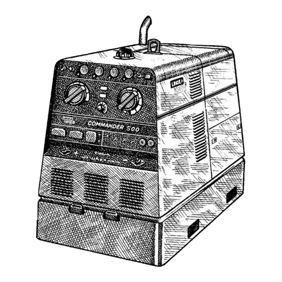
Page 20: Controls And Settings
CONTROLS AND SETTINGS All welder and engine controls are located on the case front panel. Refer to Figure B.1 and the explanations that follow. ENGINE CONTROLS (Items 1 through 8) RUN- STOP SWITCH When placed in the “RUN” position, this switch ener- gizes the fuel solenoid and other electric accessories. -
Page 21: Oil Pressure Gauge
Check engine cooling blower belt. Also, check to be sure that the welder loads are within the rating of the welder. The light will remain on when the engine has been shut down due to an over- temperature condition. -
Page 22: Welder Controls
“Cold”. 12. LOCAL The toggle switch on the control panel labeled “Local/Remote” gives the operator the option of con- trolling the output at the welder control panel or at a Provides a fine remote station. adjustment of... -
Page 23: Engine Operation
17. 120VAC RECEPTACLES These two 120VAC (5-20R) receptacles provide 120VAC for auxiliary power. Each receptacle has a 20 amp total rating. Refer to the AUXILIARY POWER RECEPTACLES section in the installation chapter for further information about these receptacles. Also refer to the AUXILIARY POWER OPERATION section later in this chapter. -
Page 24: Break-In Period
BREAK-IN PERIOD The engine used to supply power for your welder is a heavy duty, industrial engine. It is designed and built for rugged use. It is very normal for any engine to use small quantities of oil until the break-in is accom- plished. - Page 25 Table B.3 TYPICAL CURRENT RANGES DCEN (-) Tungsten Electrode 1%, 2% Diameter Thoriated in. (mm) Tungsten 0 .010 (.25) 2-15 0.020 (.50) 5-20 0.040 (1.0) 15-80 1/16 (1.6) 70-150 3/32 (2.4) 150-250 (3.2) 250-400 5/32 (4.0) 400-500 3/16 (4.8) 500-750 (6.4) 750-1000 (1) When used with argon gas.
-
Page 26: Wire Feed (Constant Voltage) Welding
WIRE FEED (CONSTANT VOLTAGE) WELD- Connect a wire feeder to the Commander 500 and set welder controls according to the instructions listed earlier in this section. The Commander 500 in the ”WIRE WELDING” position, permits it to be used with a broad range of flux cored wire (Innershield and Outershield) electrodes and solid wires for MIG welding (gas metal arc welding). -
Page 27: Commander
B-10 TABLE B.4 Commander 500 Simultaneous Welding and Power Welding Welding Output Output Range Setting 500A/40V 30-575 500A/40V 350A/30V 250A/29V 150A/27V 90A/25V * Each duplex receptacle is limited to 20 amps. ** Not to exceed 50 A per 120 VAC branch circuit when splitting the 240 VAC output. -
Page 28: Accessories
K857 28 ft. (8.5 m) or K857-1 100 ft. (30.4 m) REMOTE CONTROL - Portable control provides same dial range as the output control on the welder from a location up to the specified length from the welder. Has convenient plug for easy connection to the welder. -
Page 29: Maintenance
SAFETY PRECAUTIONS WARNING •Have a qualified technician do the maintenance and troubleshooting work. •Turn the engine off before working inside the machine. •Remove guards only when necessary and replace them when the maintenance requiring their removal is complete. •Always use the greatest care when working near moving parts. -
Page 30: Fuel Filters
7. Inspect for holes and tears by looking through the element toward a bright light. Check for damaged gas- kets or dented metal parts. Do not reuse damaged ele- ments. Protect element from dust and damage during drying and storage. 8. -
Page 31: Cooling System
The following procedure should be followed to replace the cooling blower belt: 1. Allow the machine to cool. 2. Unfasten and slide the battery holder out from the welder. 3. Disconnect the negative battery cable. 4. Remove engine case side. -
Page 32: Commander
Oil Filter Element Fuel Filter Element Water Separator Element Fuel Pre-Filter Screen Battery MAINTENANCE WELDER / GENERATOR MAINTENANCE STORAGE Store the Commander in clean, dry protected areas. CLEANING Blow out the generator and controls periodically with low pressure air. do this at least once a week in par- ticularly dirty areas. -
Page 33: How To Use Troubleshooting Guide
HOW TO USE TROUBLESHOOTING GUIDE Service and Repair should only be performed by Lincoln Electric Factory Trained Personnel. Unauthorized repairs performed on this equipment may result in danger to the technician and machine operator and will invalidate your factory warranty. For your safety and to avoid Electrical Shock, please observe all safety notes and precautions detailed throughout this manual. -
Page 34: Troubleshooting
Observe all Safety Guidelines detailed throughout this manual PROBLEMS (SYMPTOMS) Major Physical or Electrical Damage is Evident. Engine will not “crank”. Engine will “crank” but not start. Engine shuts down shortly after starting. Battery does not stay charged. If for any reason you do not understand the test procedures or are unable to perform the tests/repairs safely, contact your Local Lincoln Authorized Field Service Facility for technical troubleshooting assistance before you proceed. -
Page 35: Function Problems
POSSIBLE AREAS OF MISADJUSTMENTS(S) FUNCTION PROBLEMS 1. Idler switch in High idle position. Set switch to Auto. 2. External load on welder or auxil- iary power. Remove all external loads. 1. Poor work lead connection to work. Make sure work clamp is tightly connected to clean base metal. -
Page 36: Troubleshooting E
PROBLEMS (SYMPTOMS) No welding power output. Welder has output and no control. No auxiliary power. If for any reason you do not understand the test procedures or are unable to perform the tests/repairs safely, contact your Local Lincoln Authorized Field Service Facility for technical troubleshooting assistance before you proceed. -
Page 37: Wiring Diagram
WIRING DIAGRAM: watts ohms ENHANCED DIAGRAM DIAGRAMS HARNESS ENGINE HARNESS CONTROL COMMANDER 500 281A 229A 233A 239A 234A 224A 262A 232D 110A 109A 108A 110A 109A 108A 103A 102A 106A 104A 107A 105A 101A... -
Page 38: Connection Diagram
DIAGRAMS CONNECTION DIAGRAM: COMMANDER 500... - Page 39 DIAGRAMS CONNECTION DIAGRAM: COMMANDER 500...
- Page 40 DIAGRAMS CONNECTION DIAGRAM: COMMANDER 500...
- Page 41 DIAGRAMS CONNECTION DIAGRAM: COMMANDER 500...
- Page 42 DIAGRAMS CONNECTION DIAGRAM: COMMANDER 500...
- Page 43 CONNECTION DIAGRAM: DIAGRAMS COMMANDER 500...
- Page 44 DIAGRAMS CONNECTION DIAGRAM: COMMANDER 500...
- Page 45 DIAGRAMS CONNECTION DIAGRAM: COMMANDER 500...
- Page 46 F-10 F-10 DIAGRAMS CONNECTION DIAGRAM: COMMANDER 500...
- Page 47 F-11 F-11 DIAGRAMS CONNECTION DIAGRAM: COMMANDER 500...
- Page 48 F-12 F-12 DIAGRAMS CONNECTION DIAGRAM: COMMANDER 500...
- Page 49 F-13 F-13 DIAGRAMS CONNECTION DIAGRAM: COMMANDER 500...
-
Page 50: Dimension Print
F-14 F-14 DIAGRAMS DIMENSION PRINT COMMANDER 500... -
Page 51: Basic Course
|_|_|_|_|_|_|_|_|_|_|_|_|_|_|_|_|_|_|_|_|_| Account No. AMERICAN EXPRESS MasterCard AMERICAN EXPRESS USE THIS FORM TO ORDER: Order from: BOOK DIVISION, The Lincoln Electric Company, 22801 St. Clair Avenue, Cleveland, Ohio 44117-1199 BOOKS OR FREE INFORMATIVE CATALOGS Lincoln Welding School (ED-80) Seminar Information (ED-45) - Page 52 ● WARNING ● Spanish ● AVISO DE PRECAUCION ● French ● ATTENTION ● German ● WARNUNG ● Portuguese ● ATENÇÃO ● Japanese Chinese Korean Arabic ● ● ● ● ● ● ● ● ● ●...
- Page 53 ● ● ● ● ● ● ● ● ● ● ● ● ● ● ● ● ● ● Spanish ● PRECAUCION French ● ATTENTION German ● WARNUNG Portuguese ● ● Japanese Chinese Korean Arabic WARNING AVISO DE ATENÇÃO...
- Page 54 • World's Leader in Welding and Cutting Products • • Sales and Service through Subsidiaries and Distributors Worldwide • Cleveland, Ohio 44117-1199 U.S.A. TEL: 216.481.8100 FAX: 216.486.1751 WEB SITE: www.lincolnelectric.com...
Need help?
Do you have a question about the COMMANDER 500 IM644-A and is the answer not in the manual?
Questions and answers