Table of Contents
Advertisement
Advertisement
Table of Contents

Related Manuals for StreetStrider 8r


Summary of Contents for StreetStrider 8r
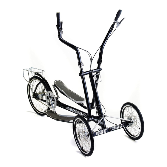
- Page 1 8r Owner’s Guide...
- Page 2 This StreetStrider 8r Owner’s Manual/Assembly Guide contains important assembly, maintenance, safety and performance information. It was written to help you get the most performance, comfort, enjoyment and safety out of your new StreetStrider. Keep this guide handy for future reference.
-
Page 3: Table Of Contents
Parts List Register at: www.streetstrider.com/register-my-streetstrider Parts Image Reference Please record your StreetStrider 8r serial number (found on UNPACKING & ASSEMBLY the frame around the bottom bracket; see photo) and other information below. Please retain your sales receipt as proof of Opening the Box purchase and keep with this information. -
Page 4: Parts Identification
PARTS IDENTIFICATION PARTS LIST The parts of the StreetStrider 8r are listed and labeled in the following table and images. DESCRIPTION HARDWARE SPECIFICATIONS STATE Main frame bone Head tube Cross bar, with joint #1 2.5 mm set screws M5 x P0.8 x L4 x W2.5... - Page 5 DESCRIPTION HARDWARE SPECIFICATIONS STATE 13 Rear rack 4 mm hex screw M5 x P0.8 x L12 x W4 Tighten washer OD12 x ID5 x T1 14 Bottle cage 4 mm hex screw M5 x P0.8 x L12 x W4 Tighten 15 Pivot joint #1 clamp 4 mm hex screw M5 x P0.8 x L12 x W4...
- Page 6 PARTS LIST (cont.) DESCRIPTION HARDWARE SPECIFICATIONS STATE 31 Brake lever w/ Phillips or 2 mm hex reach adjuster screw 32 Twist shifter clamp 3 mm hex screw Tighten 33 Shifter cable adjuster 34 Brake cable adjuster 35 Brake lever locking pin 36 Front beam pivot 8 mm hex screws M8 x P1.0 x L15 x H12 x W8, 18 mm flange...
- Page 7 DESCRIPTION HARDWARE SPECIFICATIONS STATE 42 Brake cable housing 43 Brake cable w/ adjuster barrel nut 44 Cable end 45 Steering stop screw 6 mm hex head M8 x P1.25 x L20 x H13 x W6 Tighten 12 mm nut M8 x P1.25 x L10 x W13, nylon lock Tighten 46 Bottom bracket square taper spindle...
-
Page 8: Parts Image Reference
PARTS IDENTIFICATION PARTS IMAGE REFERENCE... - Page 9 LOCKED UNLOCKED...
- Page 10 PARTS IMAGE REFERENCE (cont.) OUTBOARD INBOARD...
-
Page 12: Unpacking & Assembly
OPENING THE BOX The StreetStrider comes in a large box (Fig. 3-1A) with graphics on either side, to show which side is up. Open the box with a sharp edge to cut the top flap. Notice how the two end flaps secure each end of the folded StreetStrider inside (Figs. 3-1B). The front end beam has corner padding for protection. -
Page 13: Unpacking The Streetstrider
UNPACKING THE STREETSTRIDER Lift the folded StreetStrider out of the box, close the box flaps, and set the unit on top of The right and the box (Fig. 3-2A). left sides of the StreetStrider refer IMPORTANT: Save the box and packing material as they must be used to repack the to sides when one StreetStrider for any returns. -
Page 14: Attaching The Front Wheels
ATTACHING THE TWO FRONT WHEELS The brake cables are attached to the front wheels. Rest each front wheel against the box (Fig. 3-3A). Remove the king pin bolt from the left front beam clevis using fingers (Fig. 3-3B) or, if tight, the 6 mm hex and 17 mm open end wrenches. Slide the black steering knuckle attached to the left wheel into the clevis slot and insert the king pin bolt (Fig. - Page 15 ATTACHING THE TWO FRONT WHEELS (cont.) Figure 3-4. Attaching the two front wheels (cont.) To attach the left inboard rod end on the aluminum steering linkage to the head tube bracket, remove the nut from the rod end stud (Fig. 3-4A), insert the nut into the slot on the back side of the bracket (Fig. 3-4B), push the rod end stud into the hole to contact the nut, and screw the stud in tight using the 12 mm open end wrench (Fig.
-
Page 16: Unfolding The Head Tube
5 mm hex wrench for the female side (left side) and the 6 mm hex wrench for the male side (right side), securely tighten all three of the screws in the joint (Fig. 3-7). IMPORTANT: Keep the main frame rectangular packing foam piece to use when folding Figure 3-7. Unfolding the head tube your StreetStrider. -
Page 17: Positioning The Strider Poles
When finished adjusting strider poles, make sure the upper right and left pole positions are mirror images (Fig. 3-8B). Strider poles can be readjusted to try different positions when riding the StreetStrider. When the strider poles are aligned, the hand brake lever and twist grip shifter positions can also be adjusted to suit the rider. -
Page 18: Installing The Rear Wheel
INSTALLING THE REAR WHEEL Figure 3-9. Installing the rear wheel Remove ties and packing to free the rear wheel. Remove all packing material from the rear part of the frame to free the chain and shifter cable (Fig. 3-9A). Unscrew the hub nuts on each side of the wheel so there is a ~1 cm section of axle thread showing (Fig. 3-9B) that will be slid into the frame dropout slot. - Page 19 INSTALLING THE REAR WHEEL (cont.) With the wheel partly inside the frame, thread the chain around the hub sprocket (Fig. 3-10A). Slide the rear axle into the dropouts so that the non-turn washers (black on right side and gray on left) are on the outer side of the frame just under the chrome hub nuts. The non-turn washers have a tongue that fits into the dropout slot (Fig.
-
Page 20: Rotating The Crank Arms
ROTATING THE CRANK ARMS In order to fold the StreetStrider for packing and transporting, both crank arms are rotated in the same forward position. To set the crank arms to the correct position for striding, the left crank arm has to be rotated 180 degrees relative to the right crank arm. With the 8 mm hex wrench, unscrew the one key release crank bolt on the left crank arm (Fig. - Page 21 Make sure that some grease is present on the square spindle to facilitate crank arm installation and removal when folding the StreetStrider. For the needed leverage, use an 8 mm hex wrench or socket wrench with 8 mm hex bit with at least a 6 inch long handle.
-
Page 22: Aligning The Front Wheels
14 mm wrench. Make sure the race around the rod end ball can rotate freely on both the inboard and outboard rod ends as the StreetStrider is leaned from side to side. Check the distances one more time to make sure they are equal. -
Page 23: Checking Brake Function
(Fig. 3-15A). If rear tire does not skid, unscrew the brake adjustor nut on the right brake lever to make sure the rear rim is clamped by the rear caliper. To check the front brakes, stand in front of the StreetStrider, facing it, and pull it towards you (Fig. -
Page 24: Adjusting The Rear Hub Shifting
ADJUSTING THE REAR HUB SHIFTING With the twist grip shifter of the StreetStrider 8r in 4th gear (Fig. 3-16A), the two yellow setting lines in the gear alignment window should be together (Fig. 3-16B). If not, use the shift cable adjustor (Fig. 3-16C) to align the yellow setting lines. If there is any indication that the gears are not shifting properly after use, recheck the 4th gear setting and make an adjustment. -
Page 25: Installing The Rear Rack
INSTALLING THE REAR RACK To install the rear rack that comes with the StreetStrider 8r, you will need the 4 mm hex wrenches and 3 of the remaining stainless steel cap screws and washers (Fig. 3-17A) from the packet in the small cardboard box. Position the rack over the rear frame with three securing points (Fig. -
Page 26: Folding The Streetstrider
FOLDING THE STREETSTRIDER FOR TRANSPORTATION OR STORAGE To fold the StreetStrider and secure it for transportation or storage, reverse the unfolding procedure. Place the main frame rectangular packing foam piece over the forward section of the main frame (Fig. 3-18A). Use the 8 mm hex wrench to remove the left crank arm from the bottom bracket spindle (Fig. - Page 27 A second strap around the folded head tube and the main frame will make the folded StreetStrider more rigid for easy placement onto a rack or into a vehicle.
-
Page 28: Safety & Mechanical Information
WARNING: Many states require specific safety devices. It is your responsibility to familiarize yourself with the laws of the states where you stride and to comply with all applicable laws, including properly equipping yourself and your StreetStrider as the law requires. - Page 29 • Make sure your clothing or anything you may be carrying injury or death. Front and rear lights are not on the StreetStrider does not obstruct a reflector or light. standard equipment on this StreetStrider. If you • Stride slowly and avoid areas of heavy traffic, dark areas, intend to ride at any time under poor visibility and roads with speed limit over 35 mph.
-
Page 30: Mechanical Safety Check
StreetStrider, you assume the responsibility for the risk, not the people fingers and feet away from all moving parts while who sold you the StreetStrider, nor the people who made it, nor the people who distribute the StreetStrider is in motion, including the tires, it, nor the people who manage or maintain the roads or trails on which you ride. - Page 31 RETURN POLICY FOR MORE INFORMATION REGARDING THE STREETSTRIDER RETURN POLICY PLEASE VISIT: WWW.STREETSTRIDER.COM/RETURN-POLICY ©2014 StreetStrider International - All Rights Reserved...
Need help?
Do you have a question about the 8r and is the answer not in the manual?
Questions and answers
Need to find replacement brake handle parts and wondering if older 8 summit is convertible to quick release fold.