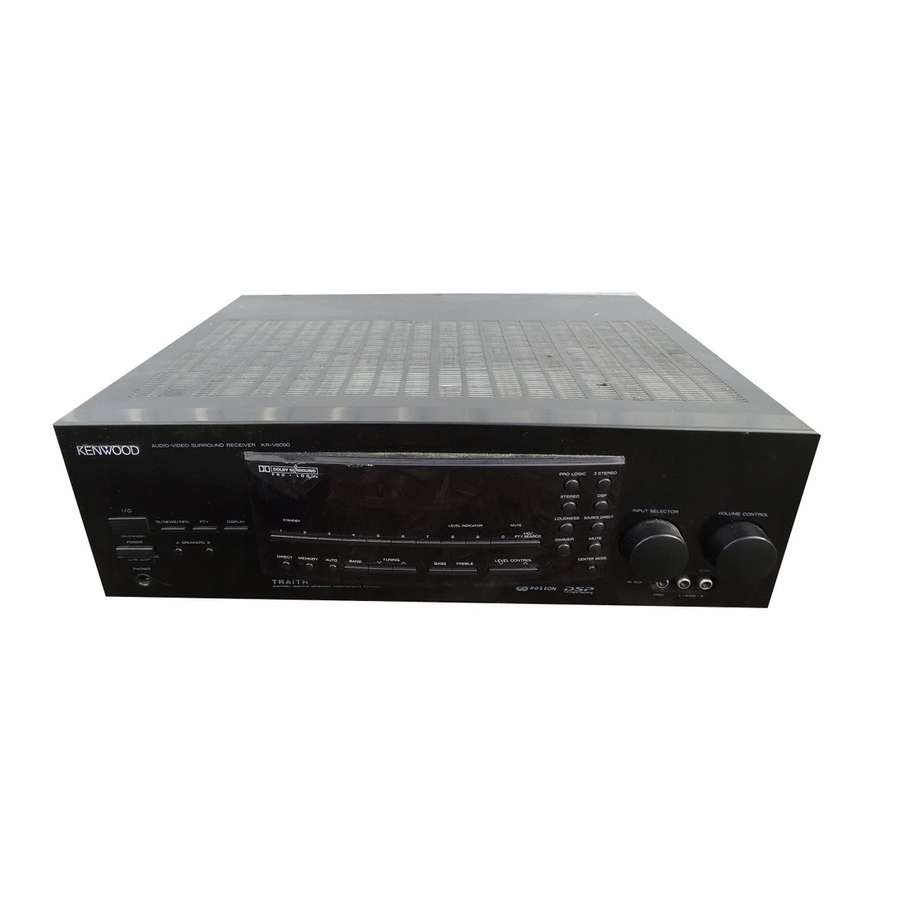
Kenwood KR-V8090 Service Manual
Audio video surround receiver
Hide thumbs
Also See for KR-V8090:
- Instruction manual (60 pages) ,
- Service manual (5 pages) ,
- Service manual (48 pages)
Table of Contents
Advertisement
QQ
AUDIO VIDEO SURROUND RECEIVER
3 7 63 1515 0
KR-V8090/KR-V9090
1060VR/1070VR
SERVICE MANUAL
KENWOOD badge *
(B43 -0302-04)
Knob(BUTTON) *
(K27-2176-04)
POWER
ON/STANDBY
A
F
L
ULL DIGITA
D
G
ECODIN
PHONES
TE
L 13942296513
Phone jack
(E11-0272-05)
Slide switch
Phono jack
(S62-0034-05)
(E63-1005-05)
PHONO
L
R
SIGNAL
GND
Lock terminal board
(E70-0052-05)
www
.
AUDIO−VIDEO SURROUND RECEIVER 1070VR
STANDBY
1
2
3
DIRECT MEMORY AUTO
BAND
SPEAKERS
B
T R A I T R
thermally reactive advanced instantaneous transistor
Knob *
(K29-)
Phono jack
(E63-0111-05)
Phono jack
(E63-0163-05)
AUDIO
CD
TAPE/MD
VIDEO1
VIDEO2
VIDEO3
ADAPTOR
REC
PLAY
REC
PLAY
PLAY
PLAY
OUT
IN
OUT
IN
IN
IN
OUT
Phono jack
(E63-0141-15)
Phono jack
(E63-0139-15)
x
ao
y
i
8
Front glass *
(B10-)
LEVEL INDICATOR
MUTE
+10
4
5
6
7
8
9
0
LEVEL CONTROL
TUNING
BASS
TREBLE
Q Q
3
6 7
1 3
Panel *
(A60-)
Miniature phone jack
(E11-0293-05)
AUX.6CH.INPUT
SYSTEM CONTROL
CENTER
L
ƒ
SL 16 XS 8
R
FRONT
SURROUND
SUB
WOOFER
IN
Phono jack
(E63-0135-15)
Screw terminal board
(E70-0049-05)
u163
.
2 9
9 4
2 8
© 1997-6/B51-5322-00 (K/K) 3145
Knob
(K29-6247-04)
PRO LOGIC 3 STEREO
STEREO
DSP
INPUT SELECTOR
VOLUME CONTROL
LOUDNESS
SOURCE DIRECT
MUTE
DIMMER
CENTER MODE
DOWN
AV AUX
VIDEO
L - AUDIO - R
Full Digital Decoding
1 5
0 5
8
2 9
9 4
Slide switch
(S31-2132-05)
Metallic cabinet
AC power cord *
(A01-3269-11)
(E30-)
Lock terminal board
AC outlet *
(E70-0065-05)
(E03-)
Power cord bushing
m
(J42-0083-05)
co
Illustration is 1070VR.
* Refer to parts list on page 36.
9 9
UP
2 8
9 9
Phone jack
(E63-1002-05)
Advertisement
Table of Contents

Related Manuals for Kenwood KR-V8090


Summary of Contents for Kenwood KR-V8090
-
Page 1: Service Manual
AUDIO VIDEO SURROUND RECEIVER 3 7 63 1515 0 KR-V8090/KR-V9090 1060VR/1070VR SERVICE MANUAL © 1997-6/B51-5322-00 (K/K) 3145 KENWOOD badge * Front glass * Knob (B43 -0302-04) (B10-) (K29-6247-04) Knob(BUTTON) * (K27-2176-04) AUDIO−VIDEO SURROUND RECEIVER 1070VR PRO LOGIC 3 STEREO STEREO... -
Page 2: Table Of Contents
1060VR/1070VR/KR-V8090/KR-V9090 3 7 63 1515 0 CONTENTS / ACCESSORIES Contents CONTENTS / ACCESSORIES ........2 WIRING DIAGRAM ............17 CONTROLS ..............3 PC BOARD ..............18 DISASSEMBLY FOR REPAIR........5 SCHEMATIC DIAGRAM ..........27 BLOCK DIAGRAM ............6 EXPLODED VIEW .............45 CIRCUIT DESCRIPTION ..........7 PARTS LIST...............46 ADJUSTMENT ............16 SPECIFICATIONS .............59... -
Page 3: Controls
1060VR/1070VR/KR-V8090/KR-V9090 3 7 63 1515 0 CONTROLS Frequency display, M.INPUT indicator Input display, SURROUND indicator (1070VR only) Preset channel display, Surround mode display Band indicators DSP indicator MEMORY indicator AC-3 M. INPUT MEMORY ******* ** AUTO indicator SURROUND AUTO STEREO indicator... - Page 4 Provide functions identical to those of the off. If you connect audio components from original remote supplied with the compo- KENWOOD and other makers to the 2 MACRO key nent you are controlling. TAPE/MD or CD jacks, you can set the...
-
Page 5: Disassembly For Repair
1060VR/1070VR/KR-V8090/KR-V9090 3 7 63 1515 0 DISASSEMBLY FOR REPAIR The method that exchanges a power transistor. 1. Remove 10 screws (1 and 2) of rear panels. 2. Remove flat cable from connector (CN851 and CN852) of printed circuit board X08 (A/3) . And, remove one screw (3). -
Page 6: Block Diagram
1060VR/1070VR/KR-V8090/KR-V9090 3 7 6 3 1 5 1 5 0 BLOCK DIAGRAM STROKE SW (X09) IC8 (X09) D111,116 u-COM (+5V) (X14) D3-5 (X14) S37,38 SCAN 8 SEL/VOL STAND BY ENCODER MATRIX FL DRIVER RETARN 5 MUTE (E,T,Q TYPE) (X14) IC1... -
Page 7: Circuit Description
1060VR/1070VR/KR-V8090/KR-V9090 3 7 63 1515 0 CIRCUIT DESCRIPTION 1. Microprocessor CXP82840-120Q/CXP82852-107Q(X08-, IC28) 1-1 Microprocessor periphery block diagram (X14) ED1 Indicator tube (11-MT-110GK) MUTE LED (X08) IC40 STANDBY LED (X14) (X14) IC1 Signal level Indicator tube driver Key matrix (uPD16311GC-AB6) RDS clock... - Page 8 1060VR/1070VR/KR-V8090/KR-V9090 3 7 63 1515 0 CIRCUIT DESCRIPTION Name I / O Description T MUTE Tuner mute signal output STEREO Tuner stereo signal input Tuner sd signal input FL STB uPD16311 (FL driver) strobe signal output FL CLK uPD16311 (FL driver) clock signal output...
- Page 9 1060VR/1070VR/KR-V8090/KR-V9090 3 7 63 1515 0 CIRCUIT DESCRIPTION 2. In order that an initial state and also back-up are done it functions. 2-1 clear of Back-up Alternating current on, while pressing a remote power key of a panel/turn off. Clearing the condition of back-up where is stored that moment, at present it, be set up to the initial state.
- Page 10 1060VR/1070VR/KR-V8090/KR-V9090 3 7 63 1515 0 CIRCUIT DESCRIPTION 3. TUNER PRESET MEMORY FREQUENCY(INITIALIZE) Channel BAND BAND BAND E1/E3 BAND 01ch 87.50MHz 87.50MHz 87.50MHz 87.50MHz 02ch 98.00MHz 98.00MHz 98.00MHz 98.00MHz 03ch 108.00MHz 108.00MHz 108.00MHZ 108.00MHZ 04ch 630kHz 630kHz 630kHz 630kHz 05ch...
- Page 11 1060VR/1070VR/KR-V8090/KR-V9090 3 7 63 1515 0 CIRCUIT DESCRIPTION The basis destination of a tuner Destination switching switch (X08) IC2 Phase locked (X14) IC1 Range of a Channel Type Band loop standard ch SP receiving frequency space frequency 87.35MHz - 108.0MHz 100kHz +10.7MHz...
-
Page 12: X09-)Ic4
1060VR/1070VR/KR-V8090/KR-V9090 3 7 63 1515 0 CIRCUIT DESCRIPTION (X09-)IC4 Control TAPE/ integrated TUNER PHONO VIDEO1 VIDEO2 VIDEO3 AV AUX circuit 27 R 26 R 25 R 24 R NJU7313 22 R 21 R 10 L 19 R 11 L 18 R... - Page 13 1060VR/1070VR/KR-V8090/KR-V9090 3 7 63 1515 0 CIRCUIT DESCRIPTION 6. PLL IC expansion port control PLL IC expansion port control list (Control data by software) Extension port Operating state name MONO RDS ATT IF ON FM ON MONO ON AM ON...
- Page 14 1060VR/1070VR/KR-V8090/KR-V9090 3 7 63 1515 0 CIRCUIT DESCRIPTION 7. Test mode • MUTE signal output Because TUNER-MUTE always becomes OFF (1) Test mode setting method condition, it isn’t possible to do control. Turn on the power supply while pressing TUNING- •...
- Page 15 1060VR/1070VR/KR-V8090/KR-V9090 3 7 63 1515 0 CIRCUIT DESCRIPTION 3 Test tone operation While displaying as follows every time it presses DIRECT key when dolby surround is working, it switches a speaker and TEST-TONE is output. By pressing DIRECT key, this work and dolby surround can be canceled.
-
Page 16: Adjustment
1060VR/1070VR/KR-V8090/KR-V9090 3 7 63 1515 0 ADJUSTMENT INPUT OUTPUT TUNER ALIGNMENT ITEM ALIGN FOR FIG. SETTINGS SETTINGS SETTINGS POINTS FM SECTION (E,T type) SELECTOR : FM Connect a DC voltmeter AUTO 98.0MHz between TP3 or MONO 1kHz,±40kHz dev. (X05-) and TP4 98.0MHz... -
Page 17: Wiring Diagram
1060VR/1070VR/KR-V8090/KR-V9090 3 7 6 3 1 5 1 5 0 WIRING DIAGRAM TUNER UNIT (X05-46XX-XX) (X08- ) (B/2) (AUDIO) MM: 2.5mV 75Ω Lch 1 PHONO Ω 1 Lch Rch 2 LINE: 200mV A SP Lch 3 AM ANT 2 Rch... -
Page 18: Pc Board
PC BOARD (Compornent side view) 3 7 63 1515 0 L 13942296513 u163... -
Page 19: Schematic Diagram
PC BOARD(Component side view) 3 7 6 3 1 5 1 5 0 1 3 9 4 2 2 9 6 5 1 3 w w w u 1 6 3 Refer to the schematic diagram for the value of resistors and capacitors. - Page 20 PC BOARD(Component side view) 3 7 6 3 1 5 1 5 0 1 3 9 4 2 2 9 6 5 1 3 w w w u 1 6 3 Refer to the schematic diagram for the value of resistors and capacitors.
- Page 21 PC BOARD(Component side view) 3 7 6 3 1 5 1 5 0 1 3 9 4 2 2 9 6 5 1 3 w w w u 1 6 3 Refer to the schematic diagram for the value of resistors and capacitors.
- Page 22 PC BOARD(Component side view) 3 7 6 3 1 5 1 5 0 1 3 9 4 2 2 9 6 5 1 3 w w w u 1 6 3 Refer to the schematic diagram for the value of resistors and capacitors.
-
Page 23: Circuit
(X05-4670-20) : 1060VR(Y)/1070VR(Y)/KR-V8090(C) TYPE The DC voltage is an actual reading measured with a high impedance type 3 7 6 3 1 5 1 5 0 voltmeter as the AM/FM signal generator is specified to the conditions as shown in the list below. -
Page 24: Nju7313
MUTE OFF:4.9V CH.SPACE (2/2) ON: 0.7V OFF: -2.3V 1u50 10u16 3.3K NJU7311AM 150K +15V 75us: 0.6v 50us:0v TA7805S FM:100kHz L 13942296513 75uS AM:10kHz FM:50kHz 50uS AM:9kHz CH SPACE LA1832 DE-EMPHASIS DSP56004FJ66 NJU7312AL NJU7313AL 14.5V +15V TA7808S u163 1060VR(Y)/1070VR(Y)/KR-V8090(C) (1/6) 1060VR/1070VR/KR-V8090/KR-V9090 Y05-3330-10... - Page 25 (X05-468X-XX) 1060VR(K,P)/1070VR(K,P)/ KR-V8090(E,T)/KR-V9090(E,T)/KR-V9090W(Q) TYPE KR-V8090/KR-V9090 (X05-4682-71) DESTINATION R16, R61-66, C53, C62, Q61- W6,13, W51,52, CF1,2 UNIT No. 68,70 56,76 54,55 COUNTRY ABB. 3 7 63 1515 0 EUROPE 2-71 L39-1351 L72-0536 1.8K 0.022 (MS3) U.K. 0-51 L39-1352 1060VR/1070VR (X05-4680-10) DESTINATION...
-
Page 26: Circuit
R84 10K MONO: 0V R80 1K w w w R81 1K R82 1K 1060VR(K,P)/1070VR(K,P)/KR-V8090(E,T)/KR-V9090(E,T)/KR-V9090W(Q) (2/6) u 1 6 3 470P R83 1K CAUTION: For continued safety, replace safety critical components only with manufacturer's recommended parts (refer to parts list). indicates safety critical components. - Page 27 -9.0V 4.7u35 (2/2) 680K -17.0V 22u35 5600P 3.9K IC14 10u50 SL16 (2/2) 3.9K 1060VR (X08-275X-XX) KR-V9090 (X08-275X-XX) KR-V8090 (X08-275X-XX) 0.068 0.016 -9.0V DESTINATION DESTINATION DESTINATION UNIT NO. W351-355 UNIT NO. W351-355 UNIT NO. W351-355 : SN761200N Q1,2 : UN5212 or D12,13 : RD6.2ES(B) or...
- Page 28 R295 100 RELAY B 2 5.4V C198 R296 100 1u50 R232 RELAY A 1 IC27 5.4V RESET w w w KR-V8090 (X08-275X-XX) KR-V9090 (X08-275X-XX) u 1 6 3 DESTINATION DESTINATION R401, R405, R401, R405, UNIT No. UNIT No. IC28 IC40...
-
Page 29: Circuit
: DAP202U or 1SS300 or MA142WA DEMODULATOR SIGNAL LINE GND LINE SAA6579 +B LINE w w w DAN202U -B LINE SN761200N 1060VR (X08-275X-XX) 1070VR (X08-275X-XX) 1060VR,KR-V8090(K) (4/6) u 1 6 3 DESTINATION DESTINATION C301- R401- C301- R401- 1070VR,KR-V9090,V9090W(K) (4/6) UNIT No. IC28 IC40 C166... - Page 30 RD10ES(B) or 6800u CANADA E03-0148 HZS11N(B2) HZS24N(B) HZS10N(B) 2-91 250V T3.15A L 250V T3.15A L 250V T800mA L 250V T1A L L07-2321 0.22 KR-V8090 DESTINATION R92,228, R125,126, R129-132,185, R267,268, R269, C9,10,21,22,25,26, C61, C129,130,138,150, C146-149, UNIT No. P1,2 E3,4 WH4-6 WH7,8...
- Page 31 3-82 CANADA CANADA CAUTION: For continued safety, replace safety critical -31V FL-B(-31V) 2-91 2-92 -31.0V components only with manufacturer's recommended KR-V8090 (X14-431X-XX) KR-V9090 (X14-431X-XX) +24V DESTINATION DESTINATION parts (refer to parts list). indicates safety critical WH5,6 WH5,6 UNIT No. UNIT No.
- Page 32 1 3 9 4 2 2 9 6 5 1 3 CANADA E83-5547-04 -28.3V LED2(AC3) POWER ON : 5.0V 2-92 KS2/SEG15(P15) DOWN MIX STANDBY : 0.2V -25.2V KS1/SEG16(P16) KR-V8090 (X14-431X-XX) LED1(STAND BY) STAND BY 5.0V DESTINATION S11,20, UNIT No. R8,33 R9,32 R10,31 R11,30 COUNTRY ABB.
-
Page 33: Exploded View
1060VR/1070VR/KR-V8090/KR-V9090 3 7 6 3 1 5 1 5 0 EXPLODED VIEW(UNIT) (M type only) L 1 3 9 4 2 2 9 6 5 1 3 650x2 650x2 u 1 6 3 Parts with the exploded numbers larger than 700 are not supplied. -
Page 34: Parts List
PANEL(for KR-V8090) H50-2404-04 ITEM CARTON CASE(for KR-V9090) A70-1115-05 REMO-CON (for KR-V9090/1070VR) A70-1117-05 REMO-CON (for KR-V9090/1070VR) KPYMC H50-2405-04 ITEM CARTON CASE(for KR-V8090) H50-2406-04 ITEM CARTON CASE(for KR-V8090) A70-1118-05 REMOTE CONTROL(for KR-V8090) H50-2407-04 ITEM CARTON CASE(for KR-V8090) H50-2408-04 ITEM CARTON CASE(for KR-V8090) - Page 35 1060VR/1070VR/KR-V8090/KR-V9090 3 7 6 3 1 5 1 5 0 PARTS LIST New Parts New Parts Parts without Parts No. are not supplied. Parts without Parts No. are not supplied. Les articles non mentionnes dans le Parts No. ne sont pas fournis.
- Page 36 1060VR/1070VR/KR-V8090/KR-V9090 3 7 6 3 1 5 1 5 0 PARTS LIST New Parts New Parts Parts without Parts No. are not supplied. Parts without Parts No. are not supplied. Les articles non mentionnes dans le Parts No. ne sont pas fournis.
- Page 37 1060VR/1070VR/KR-V8090/KR-V9090 3 7 6 3 1 5 1 5 0 PARTS LIST New Parts New Parts Parts without Parts No. are not supplied. Parts without Parts No. are not supplied. Les articles non mentionnes dans le Parts No. ne sont pas fournis.
- Page 38 1060VR/1070VR/KR-V8090/KR-V9090 3 7 6 3 1 5 1 5 0 PARTS LIST New Parts New Parts Parts without Parts No. are not supplied. Parts without Parts No. are not supplied. Les articles non mentionnes dans le Parts No. ne sont pas fournis.
- Page 39 1060VR/1070VR/KR-V8090/KR-V9090 3 7 6 3 1 5 1 5 0 PARTS LIST New Parts New Parts Parts without Parts No. are not supplied. Parts without Parts No. are not supplied. Les articles non mentionnes dans le Parts No. ne sont pas fournis.
- Page 40 DIODE 2SC3311A(Q,R) TRANSISTOR D61 -64 1SS133 DIODE 2SC2458(Y,GR) TRANSISTOR HSS104 DIODE 2SC3311A(Q,R) TRANSISTOR 1SS133 DIODE S5688B DIODE AUDIO UNIT(X09-456x-xx) for KR-V8090/1060VR D72 -87 HSS104 DIODE D72 -87 1SS133 DIODE C1 ,2 CC45FSL1H101JN CERAMIC 100PF C3 ,4 CE04KW1H100M ELECTRO 10UF 50WV...
- Page 41 1060VR/1070VR/KR-V8090/KR-V9090 3 7 6 3 1 5 1 5 0 PARTS LIST New Parts New Parts Parts without Parts No. are not supplied. Parts without Parts No. are not supplied. Les articles non mentionnes dans le Parts No. ne sont pas fournis.
- Page 42 1060VR/1070VR/KR-V8090/KR-V9090 3 7 6 3 1 5 1 5 0 PARTS LIST New Parts New Parts Parts without Parts No. are not supplied. Parts without Parts No. are not supplied. & Les articles non mentionnes dans le Parts No. ne sont pas fournis.
-
Page 43: Nju7313
1060VR/1070VR/KR-V8090/KR-V9090 3 7 6 3 1 5 1 5 0 PARTS LIST New Parts New Parts Parts without Parts No. are not supplied. Parts without Parts No. are not supplied. Les articles non mentionnes dans le Parts No. ne sont pas fournis. - Page 44 1060VR/1070VR/KR-V8090/KR-V9090 3 7 6 3 1 5 1 5 0 PARTS LIST New Parts New Parts Parts without Parts No. are not supplied. Parts without Parts No. are not supplied. ¡ ™ Les articles non mentionnes dans le Parts No. ne sont pas fournis.
- Page 45 1060VR/1070VR/KR-V8090/KR-V9090 3 7 6 3 1 5 1 5 0 PARTS LIST New Parts New Parts Parts without Parts No. are not supplied. Parts without Parts No. are not supplied. £ ¢ Les articles non mentionnes dans le Parts No. ne sont pas fournis.
-
Page 46: Circuit
1060VR/1070VR/KR-V8090/KR-V9090 3 7 6 3 1 5 1 5 0 PARTS LIST New Parts New Parts Parts without Parts No. are not supplied. Parts without Parts No. are not supplied. ∞ § Les articles non mentionnes dans le Parts No. ne sont pas fournis. -
Page 47: Specifications
BASS ............±8 dB (at 100 Hz) TREBLE ..........±8 dB (at 10 kHz) u163 LOUDNESS control VOLUME at -40dB level..+7 dB(100 Hz), +3 dB(10 kHz) KENWOOD follows a policy of continuous advancements in development. For this reason specifications may be changed without Notes notice. -
Page 48: Circuit
P.O BOX 55-2791, Piso 6 plaza Chase, Cl. 47 y Aquilino de la Guardia Panama, Republic de Panama KENWOOD ELECTRONICS U.K. LIMITED KENWOOD House, Dwight Road, Watford, Herts., WD1 8EB., United Kingdom KENWOOD ELECTRONICS BENELUX N.V. Meachelsesteenweg 418, B-1930 Zaventem, Belgium KENWOOD ELECTRONICS DEUTSCHLAND GMBH Rembrücker Str.
Need help?
Do you have a question about the KR-V8090 and is the answer not in the manual?
Questions and answers