Table of Contents
Advertisement
Quick Links
ALINCO, INC.
Yodoyabashi Dai-bldg 13F
4-4-9 Koraibashi, Chuo-ku, Osaka 541-0043 Japan
Phone: +81-6-7636-2362 Fax: +81-6-6208-3802
http://www.alinco.com
E-mail:export@alinco.co.jp
UHF FM Transceiver 8 PMR446 channels.
Use of this device is authorized in all EU and EFTA
member states (CH/ICE/LI/NOR).
Copyright Alinco, lnc. PS0804/FNEH-NB
Printed in China
Advertisement
Table of Contents

Related Manuals for Alinco DJ-A46


Summary of Contents for Alinco DJ-A46
- Page 1 Yodoyabashi Dai-bldg 13F 4-4-9 Koraibashi, Chuo-ku, Osaka 541-0043 Japan Phone: +81-6-7636-2362 Fax: +81-6-6208-3802 http://www.alinco.com E-mail:export@alinco.co.jp UHF FM Transceiver 8 PMR446 channels. Use of this device is authorized in all EU and EFTA member states (CH/ICE/LI/NOR). Copyright Alinco, lnc. PS0804/FNEH-NB Printed in China...
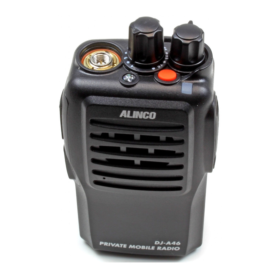
- Page 2 PRIVATE MOBILE RADIO DJ-A46 Instruction Manual Thank you for purchasing your new Alinco transceiver. Please read this manual carefully before using the product to ensure full performance, and keep this manual for future reference as it contains information on after-sales service.
- Page 4 Introduction Thank you very much for purchasing this excellent Alinco transceiver. Our products are ranked among the finest in the world. This radio has been manufactured with state of the art technology and it has been tested carefully at our factory. It is designed to operate to your satisfaction for many years under normal use.
- Page 5 Alinco accessories and the radio has not been disassembled by the customer. The factory has tested and made the equipment compatible to IP54 certification during engineering.
- Page 6 Features ■ 128 PC-programmable channels(16ch x 8groups) ■ Li-Ion battery pack and stand-charger as standard accessories ■ Voice Compander(Reduce Noise & enhance audio clarity) ■ Inversion Scramble ■ Sub-tone(CTCSS/DCS) Encode/Decode ■ VOX built-in(An optional earphone-microphone is necessary) Conformity Symbols Tested to comply MIL-STD-810G -Shock: Method 514.6/I,IV -Vibration: Method 516.6/I...
- Page 7 Alert Environment and condition of use Use of this product may be prohibited or illegal outside of your country. Be informed in advance when you travel. It is recommended that you check local traffic regulations regarding the use of a radio equipment while driving.
- Page 8 The manufacturer declines any responsibilities against loss of life and property due to a failure of this product when used with or as a part of a device made by third parties. Use of third party accessory may result in damage to this product. It will void our warranty for repair. Handling this product Be sure to reduce the audio output level to minimum before using an earphone or a headset.
- Page 9 Securely plug the adapter into the wall outlet. Insecure installation may result in short-circuit, electronic shock and/or fire. Do not use the adapter if the plug or socket contacts are dirty. Overheating and/or short-circuiting may result in fire, electric shock and/or damage to the product. In case of emergency In case of the following situation(s), please turn off the product, switch off the source of power, then remove or unplug the power-cord.
- Page 10 Alert Environment and condition of use Do not use the product in proximity to a TV or a radio. It may cause interference or receive interference. Do not install in a humid, dusty or insufficiently ventilated place. It may result in electric shock, fire and/or malfunction.
- Page 11 Use a clean, dry cloth to wipe off dirt and condensation from the surface of the product. Never use thinner or benzene for cleaning. Check with your local waste officials for details on recycling or proper disposal of the electronics product, battery-packs and accessories in your area.
-
Page 12: Table Of Contents
TABLE OF CONTENTS STANDARD ACCESSORIES/OPTIONAL ACCESSORIES ..........1 Standard Accessories ......................... 1 BATTERY INFORMATION ....................2 Charging Operation ..........................2 Battery Charger Type .......................... 2 Notice for Charging Battery ......................... 2 How to Charge the battery pack ......................4 How to Store the Battery ........................6 PREPARATION ........................ - Page 13 TABLE OF CONTENTS Group Selection ..........................13 Receiving ............................13 Transmitting ............................13 Emergency Alarm Function ......................... 14 Resetting ............................. 14 ADVANCED OPERATIONS( [PF1] & [PF2] KEY ) ............. 15 Monitor ..............................15 Momentary Monitor ..........................15 Temporary Deletion of the Interfering Channel from scanning ............15 Squelch Levels Enquiry ........................
- Page 14 OPTIONAL ACCESSORIES ....................2 1 RECOMMENDED INSTALLATION OF EARPHONE MICROPHONE ......... 22 TECHNICAL SPECIFICATIONS ..................23 DJ-A46 TECHNICAL SPECIFICATIONS .................... 23 TROUBLE SHOOTING GUIDE ................... 24 ATTACHED CHARTS ......................26 Preset Channel Frequency Chart (Reset won't delete these channels) ..........26...
-
Page 15: Standard Accessories/Optional Accessories
STANDARD ACCESSORIES Standard Accessories Li-ion Battery Pack Charger AC Adaptor Belt Clip Instruction Hand Strap Manual NOTE: Accessories may differ depending on the version you have purchased. Please contact your local dealer for details of standard accessories and the warranty-policy before purchase. Professional FM Transceiver... -
Page 16: Battery Information
Battery Charger Type Please use Alinco's designated charger, other models may cause explosion. After installing the battery pack, if the radio displays low battery with red flashing lamp or voice prompt, please charge the battery. - Page 17 BATTERY INFORMATION Caution: ▼ Risk of explosion, generation of heat or leak of chemicals inside if the battery is replaced by an incorrect type or reverse polarity. Use always the recommended types of batteries in this manual only. ▼ The battery pack isn't fully charged when shipped. It must be charged before use. ▼...
-
Page 18: How To Charge The Battery Pack
BATTERY INFORMATION How to Charge the battery pack 1.Plug the AC adaptor into the AC outlet, then plug into the DC jack, the indicator lights orange for 1 second and goes out---waits to charge. 2.Slide the battery or transceiver with battery into the Ac Input charger;... - Page 19 BATTERY INFORMATION NOTE: ▲ Trouble means battery heating, short-circuit or charger malfunction. Remove the battery pack from the charger immediately and contact to your local dealer for services. ▲ The max trickle pre-charging time is 30 minutes. In case the red indicator continues to blink longer, please stop charging and consult with your local dealer for services.
-
Page 20: How To Store The Battery
BATTERY INFORMATION How to Store the Battery 1.The battery should be kept in the status of 50% discharge when storing. 2.Remove the battery pack from the radio and keep it in a cool, dry place. 3.Keep away from source of heat and direct sunlight. Note: Incorrect storage will damage both the battery pack and the radio. -
Page 21: Preparation
INSTALLATION & CONNECTION Installing / Removing the Li-ion Battery 1.Match the three grooves of the battery pack with the corresponding guides on the back of the transceiver, then push it. 2.Press the battery and transceiver firmly together until the release latch on the top of the transceiver locks. -
Page 22: Accessories
INSTALLATION & CONNECTION Accessories Open the jack cover and insert the accessory plug into the jack,as shown. When the accessory is not used, please be sure to close the cover securely. NOTE: 1.To keep the radio dust and splash resistant, the cover must be closed properly with the original supplied cover. -
Page 23: Getting Acquainted
GETTING ACQUAINTED DJ-A46 PRIVATE MOBILE RADIO Professional FM Transceiver... - Page 24 GETTING ACQUAINTED Antenna POWER / VOLUME Switch: To turn on/off the power and adjust the audio level. Jacklight: White is lit when the alarm key is pressed. Emergency Alarm Key (1) Under the standby conditions, press this key for 1 second to enable alarm function. Press this key again to exit the alarm status.This is optional and PC preprogramming is required.
-
Page 25: Indicator Status And Beep
GETTING ACQUAINTED Indicator Status and Beep Transceiver emits a low voltage beep at intervals of 60 seconds, Low battery voltage warning and red light blinks. TX/Reading data Red is lit while transmitting or reading the data while programming. RX/Writing data Green is lit whilereceiving or writing the data while programming. -
Page 26: Basic Operations
BASIC OPERATIONS Switch on / off Transceiver Turn 【 POWER 】 / 【 VOLUME 】 dial clockwise to power on. Turn it counterclockwise to power off. Adjusting Audio output level Press and release PF1 key to monitor white noise to refer to the current audio level. Turn 【... -
Page 27: Group Selection
BASIC OPERATIONS Group Selection By PC-preprogramming, 128 channels can be assigned in total which are divided into 8 groups with 16 channels in each group. If different groups are being programmed, set the selector knob at "1" then press and hold [PF2] to turn on. Still holding [PF2] for another 2 seconds, it will announce "Group 1". -
Page 28: Emergency Alarm Function
BASIC OPERATIONS Emergency Alarm Function (PC pre-programming required) Press the emergency alarm key for over 1 second to start the Emergency Alarm Function. Once activated, it will generate alarm sound, start transmitting to send alarm beeps. Turn off then turn on again or pressing Emergency Alarm key again to exit the function. -
Page 29: Advanced Operations( [Pf1] & [Pf2] Key )
ADVANCED OPERATIONS ( [PF1] & [PF2] KEY ) The [PF1] and [PF2] keys are programmable by using programming software. Monitor Under the standby conditions, pressing and releasing the programmed key, it beeps and enters the monitor state. While in Monitor, it ignores CTCSS / DCS decode and enables monitoring all incoming signals. -
Page 30: Squelch Levels Setup
ADVANCED OPERATIONS ( [PF1] & [PF2] KEY ) Squelch Levels Setup Under the standby conditions, pressing and holding the programmed key, it will set the squelch and announces the level by voice. Scan Scan function is to automatically search the busy channels. Under the standby conditions, pressing and holding the programmed key, a beep sounds and starts scanning. -
Page 31: Whisper
ADVANCED OPERATIONS ( [PF1] & [PF2] KEY ) Whisper Under the standby conditions, pressing the programmed key, it beeps and activates whisper function. This feature is handy in quiet place, you can talk in lower voice than usual. Pressing this key again, it beeps twice and exits whisper function. -
Page 32: Preset Operations( Function Setup )
PRESET OPERATIONS ( FUNCTION SETUP ) Following features can be set by using programming software. CTCSS / DCS Encode / Decode It enables the CTCSS/DCS encode/decode setting. Pre-programming is necessary and usually not recommended for general users. Busy Channel Lockout BCLO is to restrict transmitting while RX signal is received. -
Page 33: Channel Scan Skip
PRESET OPERATIONS ( FUNCTION SETUP ) Channel Scan Skip Users can choose whether to set current channel as Scan Skip by programming software. Transceiver will skip current channel during scan when it is set as Scan Skip. TX OFF Once this function is enabled, [PTT] key becomes invalid and it works only as a receiver. Battery Save Setup This function prevents useless battery consumption by switching the power ON/OFF at a fixed ratio if there is no key operation or receiving signal for a continuous period of 5 seconds or more. -
Page 34: Tot Re-Transmitting Time Setup
PRESET OPERATIONS ( FUNCTION SETUP ) TOT Re-transmitting Time Setup This is the penalty time before resuming the normal operation condition, once TOT stopped the transmission. Voice Operated Transmission (VOX: An optional earphone-microphone is necessary) When this function is on, the transmitting can be started by voice, no need to press [PTT] key. NOTE: VOX is not usable in noisy areas as it may start transmitting by the back noise. -
Page 35: Optional Accessories
OPTIONAL ACCESSORIES EBC-34 Belt Clip EBP-87 Li-ion Battery Pack (DC 7.4V 1500mAh) EBP-88 Li-ion Battery Pack (DC 7.4V 1700mAh) EDC-189 Li-ion Battery Charger EDC-191E AC Adaptor (220V) EME-56A Earphone Microphone EMS-76 Speaker microphone Professional FM Transceiver... -
Page 36: Recommended Installation Of Earphone Microphone
RECOMMENDED INSTALLATION OF EARPHONE MICROPHONE Earphone Use a clip to fix with collar. Clip the PTT unit closer to your mouth. Carry the radio on the side or the back of your body, and the cable should go around the back as shown. Clamp the excessive length of cable at your waist. -
Page 37: Technical Specifications
TECHNICAL SPECIFICATIONS DJ-A46 TECHNICAL SPECIFICATIONS General Transmitting Frequency Range 446.00625 – 446.09375 MHz Power Output 0.5W Channel Capacity 128 channels Modulation 8K50F3E(FM) Operating Voltage 7.4V DC ±20% Max.deviation ±2.5KHz More than 14 Hours (1500mAh), by Battery Life 5-5-90 work cycle Receiving Frequency Stability ±2.5ppm... -
Page 38: Trouble Shooting Guide
TROUBLE SHOOTING GUIDE Problem Corrective Action A.The battery may be exhausting. Recharge or replace the battery. B.The battery may not be installed correctly. Remove the battery No power and install it again. C.The power switch is broken; send it to local dealers to repair. D.Battery life is end;... - Page 39 C.Earphone jack is broken, please contact with local dealers to repair. NOTE: Alinco guarantees the supply of minimum-necessary spare parts such as battery-packs, components and mechanical parts for at least 5 years after the production of this product is terminated except in case of accidents beyond control.
-
Page 40: Attached Charts
ATTACHED CHART Preset Channel Frequency Chart (Reset won't delete these channels) Group Channel Frequency CTCSS/DCS Group Channel Frequency CTCSS/DCS 446.05625 110.9 446.00625 94.8 446.06875 114.8 446.09375 88.5 446.08125 118.8 446.03125 103.5 446.09375 123.0 446.06875 79.7 446.00625 127.3 446.04375 118.8 446.01875 131.8 446.01875 123.0...
Need help?
Do you have a question about the DJ-A46 and is the answer not in the manual?
Questions and answers