
Related Manuals for Whirlpool AKM106


Summary of Contents for Whirlpool AKM106
-
Page 1: Table Of Contents
MICROWAVE OVEN AKM106 HOME APPLIANCES SERVICE Manual CONTENTS MICROWAVE OVEN 1. Precaution 2. Specifications 3. Operating Instructions 4. Disassembly and Reassembly 5. Alignment and Adjustments 6. Troubleshooting 7. Exploded Views and Parts List 8. PCB Diagrams 9. Schematic Diagrams WHIRLPOOL... -
Page 2: Precaution
1. Precaution Follow these special safety precautions. Although the microwave oven is completely safe during ordinary use, repair work can be extremely hazardous due to possible exposure to microwave radiation, as well as potentially lethal high voltages and currents. 1-1 Safety precautions ( 1. - Page 3 Pretaution 1-2 Special Servicing Precautions (Continued) 16. When checking the continuity of the witches or transformer, always make sure that the power is OFF, and one of the lead wires is disconnected. 17. Components that are critical for safety are indicated in the circuit diagram by shading, 18.
-
Page 4: Specifications
2. Specifications 2-1 Table of Specifications MODEL AKM106 ITEM TIMER 99 MINUTES 99 SECONDS POWER SOURCE 120V/60HZ, AC POWER CONSUMPTION MICROWAVE : 1.4KW(IEC), 1.25KW(CNS) OUTPUT POWER FROM90W TO900W (10 LEVEL POWER ; IEC) (IEC-705 TEST PROCEDURE) OPERATING FREQUENCY 2,450MHz MAGNETRON... -
Page 5: Operating Instructions
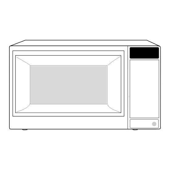
5. Hold / Timer Button 6. More / Less Button 7. Pause / Cancel Button 8. Start Button 9. Instant Cook Button 10.Auto Reheat Button 11.Number Key Button AKM106 3-2 Features & External Views Ventilation Holes Light Door Safety Interlock Holes Control Panel... -
Page 6: Disassembly And Reassembly
4. Disassembly and Reassembly 4-1 Replacement of Magnetron, Motor Assembly and Lamp Remove the magnetron including the shield case, Cover Air permanent magnet, choke coils and capacitors (all of which are contained in one assembly). Thermo S/W BKT-T.C.O Lamp 1. Disconnect all lead wires from the magnetron and lamp. - Page 7 Disassembly and Reassembly 4-3 Replacement of Door Assembly 4-3-1 Removal of Door Assembly Remove screws securing the upper hinge and Upper Hinge lower hinge. Then remove the door assembly. Screw Lower Hinge Screw 4-3-2 Removal of Door "C" Insert flat screwdriver into the gap between Door Door "C"...
- Page 8 Disassembly and Reassembly 4-3-5 Reassembly Test After replacement of the defective component parts of the door, reassemble it and follow the instructions below for proper installation and adjustment so as to prevent an excessive microwave leakage. 1. When mounting the door to the oven, be sure to adjust the door parallel to the bottom line of the oven face plate by moving the upper hinge and lower hinge in the direction necessary for proper alignment.
- Page 9 Disassembly and Reassembly 4-6 Replacement of Control Circuit Board 4-6-1 Removal of Control Box Assembly 1. Be sure to ground any static electric charge in your body and never touch the control circuit. 2. Disconnect the connectors from the control Screw circuit board.
-
Page 10: Alignment And Adjustments
3. Before touching any oven components or wiring, always unplug the oven from its power source and discharge the high voltage capacitor. 5-1 High Voltage Transformer 1. Remove connectors from the transformer terminals Filament Terminals and check continuity. 2. Normal resistance readings are as follows: Primary MODEL AKM106 Terminals Secondary ¡ Filament Shows Continuity Primary 0.40W ¡... -
Page 11: High Voltage Capacitor
Alignment and Adjustments 5-4 High Voltage Capacitor 1. Check continuity of the capacitor with the meter set at the highest resistance scale. 2. Once the capacitor is charged, a normal capacitor shows continuity for a short time, and then indicates 9MW. 3. - Page 12 Alignment and Adjustments 5-8 Output Power of Magnetron CAUTION MICROWAVE RADIATION PERSONNEL SHOULD NOT ALLOW EXPOSURE TO MICROWAVE RADIATION FROM MICROWAVE GENERATOR OR OTHER PARTS CONDUCTING MICROWAVE ENERGY. The output power of the magnetron can be measured by performing a water temperature rise test. Equipment needed : * Two 1-liter cylindrical borosilicate glass vessel (Outside diameter 190 mm) * One glass thermometer with mercury column...
-
Page 13: Procedure For Measurement Of Microwave Energy Leakage
Alignment and Adjustments 5-10 Procedure for Measurement of Microwave Energy Leakage 1) Pour 275±15cc of 20±5ûC(68±9ûF) water in a beaker which is graduated to 600cc, and place the beaker in the center of the oven. 2) Start to operate the oven and measure the leakage by using a microwave energy survey meter. -
Page 14: Troubleshooting
6. Troubleshooting PRECAUTION 1. CHECK GROUNDING BEFORE CHECKING FOR TROUBLE. 2. BE CAREFUL OF THE HIGH VOLTAGE CIRCUIT. 3. DISCHARGE THE HIGH VOLTAGE CAPACITOR. 4. WHEN CHECKING THE CONTINUITY OF THE SWITCHES OR TRANSFORMER, DISCONNECT ONE LEAD WIRE FROM THESE PARTS AND THEN CHECK CONTINUITY WITHOUT THE POWER SOURCE ON. - Page 15 Troubleshooting 6-1 Electrical Malfunction(continued) SYMPTOM CAUSE CORRECTIONS Oven lamp and fan motor turn on 1. Misadjustment or loose wiring Adjust door and latch switches. of primary latch switch 2. Defective primary latch switch Oven can program but timer 1. Open or loose wiring of secondary Adjust door and interlock switches.
-
Page 16: Exploded Views And Parts List
7. Exploded Views and Parts List 7-1 Exploded Views... -
Page 17: Main Parts List
DIODE-H.V;HVR-1X-32B-12 2501-001011 C-OIL;910nF,2100V,BK,54x35x75mm,20mm DE26-10134A TRANS-H.V;SHV-5574UC1,120V,2160V/3.35V,6 DE63-90167A CUSHION-HVT;NEOPRENE/RUBBER,T36.5,W40,L50 CAVITY DE61-40066A FOOT;PP,BLK,-,-,3RD-W DE80-10002A BASE-PLATE;SGCC,T(0.8),W(404),L(633),MW65 DE31-10154A MOTOR-DRIVE;M2HJ49ZR02,ST-16,50/60HZ,- DE47-20033A THERMOSTAT;PW-2N,80/70,125V15A/250V7.5A,1 B/MOTO DE71-60164F COVER-MGT;PP(TB53/A353),30G,MW5430/6430 DE94-00066B ASSY DOOR;AKM106,-,WHIRLPOOL DE94-00041B ASSY CONTROL-BOX;AKM106,-,WHIRLPOOL DE74-20002A TRAY-COOKING;GLASS,T6,PI360,1.2CUFT,NEG DE92-90189B ASSY-GUIDE ROLLER;D16.5,STD DE67-60002A COUPLER;PPS,5GR,BRN,M97G45 : Warning : Option Parts :Electrostatically Sensitive Devices... -
Page 18: Door Parts List
Exploded Views and Parts List 7-3 Door Parts List Ref. No. Parts No. Description/Specification Q'ty Remarks DE67-20167A SCREEN-DOOR;ACRYL,T1.5,W238.6,L440,WHT,MW6 DE02-00125A TAPE-DOUBLE FACE;ACRYL,T0.45,W9,WHT,WF103,#4420 DOOR-A DE64-40276H DOOR-A;ABS(HR0370),-,-,-,-,AKM106,- DE92-50128E ASSY DOOR-E;COATING,WHT,MW6574W,-,-,-,- DE64-40010A DOOR-C;PP(TB53),T1.5,WHT,MW6574W,-,-, DE01-00004A FILM-DOOR;PE,T0.15,W189,L331,NTR,1.2CU.F DE64-40006B DOOR-KEY;POM(TC3005),T2,12GR,WHT,MW5574 DE61-70128A SPRING-KEY;HSW3,PI0.6,D5,BLUING,-,-,- DE61-80002A HINGE-UPPER;SCP1,T2.3,26,77,ZPC3,WHT,CE945 DE61-80003A HINGE-LOWER;SCP1,T2.3,26,77,ZPC3,WHT,CE945 7-4 Control Parts List Ref. -
Page 19: Standard Parts List
Exploded Views and Parts List 7-6 Standard Parts List Parts No. Description / Specification Q'ty Remarks DE60-10053A SCREW-TAP PH;PH,M4,L10,FEFZY C-TCO DE60-10053A SCREW-TAP PH;PH,M4,L10,FEFZY M/GEAR DE60-10080A SCREW-WASHER;M5,L12,2S DE60-10080A SCREW-WASHER;M5,L12,2S DE60-10082H SCREW-A;2S-4X12,TOOTHED DE60-10082H SCREW-A;2S-4X12,TOOTHED B-LATC DE60-10082H SCREW-A;2S-4X12,TOOTHED BASE DE60-10082H SCREW-A;2S-4X12,TOOTHED C-PANE DE60-10082H SCREW-A;2S-4X12,TOOTHED CV/AIR DE60-10082H... - Page 20 8. P.C.B Diagrams 8-1 P.C.B Diagrams...
- Page 21 P.C.B Diagrams 8-2 P.C.B Parts List Parts No. Description / Specification Q'ty Remarks 0401-001002 DIODE-SWITCHING;1N4148M,100V,200mA,DO-34,TP D05,D06,D07,D08,D09,D10,D11,D12 0401-001002 DIODE-SWITCHING;1N4148M,100V,200mA,DO-34,TP D13,D14,D15,D16,D17,D18,D19,D20 0402-000559 DIODE-RECTIFIER;D4G,400V,1A,T-1 D01,D02,D04 0403-000525 DIODE-ZENER;1N4733A,5.1V,5%,1W,DO-41,TP ZD01,ZD02,ZD03 0501-000283 TR-SMALL SIGNAL;KSA539,PNP,400mW,TO-92,TP,120- 0504-001014 TR-DIGITAL;KSR1005,NPN,300mW,4.7K-10K,TO- Q01,Q06,Q07,Q09,Q10 0504-001015 TR-DIGITAL;KSR2005,PNP,300mW,4.7K-10K,TO- Q02,Q03,Q04,Q05 1405-001010 VARISTOR;270V,4500A,16x19mm,BK ZNR1 2001-000037 R-CARBON(S);330OHM,5%,1/2W,AA,TP,- R03,R04 2001-000273 R-CARBON;100KOHM,5%,1/8W,AA,TP,- R17,R21...
-
Page 22: Schematic Diagrams
9. Schematic Diagrams 9-1 Schematic Diagrams WARNING POWER MUST BE DISCONNECTED BEFORE SERVICING THIS APPLINACE CAVITY PRIMARY S/W FUSE H. V. TRANSFORMER 250V20A 130V 120V 120V POWER CORD H. V. CAPACITOR AC 120V/60Hz MAGNETRON POWER RELAY (SECONDARY INTERLOCK) P.C.BOARD 1. INPUT : 120V 60HZ DOOR NOTE: CIRCUIT SHOWN WITH DOOR IS OPENED POSITION.
Need help?
Do you have a question about the AKM106 and is the answer not in the manual?
Questions and answers