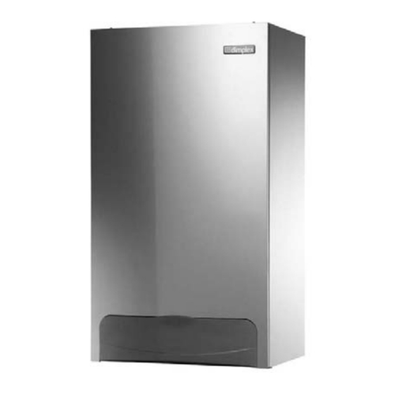
Summary of Contents for Glen Dimplex System 18
- Page 1 System 18 System 30 System Condensing Boilers User’s Operating Instructions These instructions should be left with the user © Dimplex Boilers 2008...
- Page 2 Read these instructions carefully before trying to operate the appliance. GAS COUNCIL NUMBERS Natural Gas Dimplex System 18 - Gas Council Appliance No: 41 149 02 Dimplex System 30 - Gas Council Appliance No: 41 149 01 Control Panel Fig. 1 CONTROL PANEL Fig.
-
Page 3: Using The Boiler
USING THE BOILER Green SYSTEM PRESSURE GAUGE The normal operating water pressure is shown when the needle is in the GREEN section of the gauge between 1 and 2 bar. If the pressure drops too low the system will need topping up via the filling loop. -
Page 4: Problem Solving
PROBLEM SOLVING STEP BY STEP GUIDE Boiler Not Working Check that the gas supply is turned on. Consult gas supplier Are other gas appliances working? Is the central heating pressure between 1 +2 Top up the system pressure bar (needle in the green)? See section 1.9 Is the timer on? Set timer to on... - Page 5 2. Where an open flued (B23) system is used then an air vent must be provided in the same room or internal space of the flue duct air inlet, with a minimum free area of: System 18 = 88cm System 30 = 159cm 3. These dimensions include the necessary clearance around the boiler for case removal, spanner access and air movement.
-
Page 6: Error Codes
ERROR CODES The boiler is in an ERROR state when there is an error code flashing on the back lit display. CH = C C entral Heating BCC = Boiler Chip Card Press and release the RESET button, the control tries to i i nitiate a restart if possible ERROR CODE DESCRIPTION REASON... -
Page 7: Additional Information
ADDITIONAL INFORMATION BOILER LOGBOOK EMERGENCY The logbook is included inside the Installation instructions. This WARNING - If a gas leak is suspected or exists, turn the gas logbook should be completed by your installer to verify that OFF at the incoming mains (adjacent to the meter), Do not the correct installation and commissioning procedure was operate any electrical switches. - Page 8 Part of the Glen Dimplex Group Glen Dimplex Boilers is continually improving its products and therefore reserve the right to change product specifications without prior notice. Errors & omissions excepted. S A L E S A N D S E R V I C E H E L P L I N E : 0 8 4 4 3 7 1 1 1 1 1 Part No: 751263 - Issue 3 - 07/07/10 ©...


Need help?
Do you have a question about the System 18 and is the answer not in the manual?
Questions and answers