Advertisement
48pp MANUAL SPREADS
19/10/10
08:36
Page 1
Glen Dimplex Boilers is continually improving its products and therefore
reserve the right to change product specifications without prior notice.
SALES AND SERVICE HELPLINE: 0844 371 1111
Part No: 751253 - Issue 3 - 7/07/10
Glen Dimplex Boilers
Stoney Lane
Prescot
Merseyside. L35 2XW
For all telephone enquiries call:
0844 371 2222
website:
www.glendimplexboilers.com
Part of the Glen Dimplex Group
Errors & omissions excepted.
© Dimplex Boilers 2008
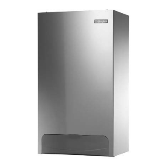
Combi 24
Combi 30
Combi 38
Combination Condensing Boilers
Installation and
Servicing Instructions
These instructions should be left with the user
© Dimplex Boilers 2008
Advertisement
Table of Contents

Related Manuals for Glen Dimplex Combi 24


Summary of Contents for Glen Dimplex Combi 24
- Page 1 Part of the Glen Dimplex Group Installation and Servicing Instructions Glen Dimplex Boilers is continually improving its products and therefore reserve the right to change product specifications without prior notice. Errors & omissions excepted. These instructions should be left with the user SALES AND SERVICE HELPLINE: 0844 371 1111 ©...
-
Page 2: Warranty Terms And Conditions
Dimplex Combi 30 - Gas Council Appliance No: 4 4 7 149 02 Commissioned by (print name) Company Name Dimplex Combi 24 - Gas Council Appliance No: 4 4 7 149 03 Company Address Telephone Number Commissioning Date To be completed by the customer on receipt of a Building Regulations Compliance Certificate * :... - Page 3 48pp MANUAL SPREADS 19/10/10 08:36 Page 3 17.0 BENCHMARK CONTENTS SERVICE RECORD It is recommended that your hot water system is serviced regularly and that the appropriate Service Record is completed. SECTION DESCRIPTION PAGE Service Provider Before completing the appropriate Service Record below, please ensure you have carried out the service as described in the manufacturer’s Introduction instructions.
- Page 4 48pp MANUAL SPREADS 19/10/10 08:36 Page 4 INTRODUCTION 17.0 BENCHMARK MAINS PRESSURE HOT WATER STORAGE SYSTEM COMMISSIONING CHECKLIST BUILDING REGULATIONS AND BENCHMARK CHECKLIST INSTALLATION, COMMISSIONING, SERVICE & REPAIR Building Regulations (England & Wales) require notification of This appliance must be installed in accordance with the This Commissioning Checklist is to be completed in full by the competent person who commissioned the storage system as a means of the installation of a heating appliance to the relevant Local manufacturer’s instructions and the regulations in force.
- Page 5 48pp MANUAL SPREADS 19/10/10 08:36 Page 5 17.0 BENCHMARK INTRODUCTION SERVICE RECORD LEGISLATION It is recommended that your heating system is serviced regularly and that the appropriate Service Record is completed. The appliance is suitable only for installation in GB and IE and GAS LEAKS Service Provider should be installed in accordance with the rules in force, and...
- Page 6 48pp MANUAL SPREADS 19/10/10 08:36 Page 6 INTRODUCTION 17.0 BENCHMARK GAS BOILER SYSTEM COMMISSIONING CHECKLIST SAFE MANUAL HANDLING This Commissioning Checklist is to be completed in full by the competent person who commissioned the boiler as a means of demonstrating 1.
-
Page 7: Error Codes
48pp MANUAL SPREADS 19/10/10 08:36 Page 7 16.0 ERROR CODES BOILER LAYOUT The boiler is in an ERROR state when there is an error code flashing on the back lit display. CH = Central Heating DHW = Domestic Hot Water BCC = Boiler Chip Card Press and release the RESET button, the control tries to initiate a restart if possible Expansion Vessel... -
Page 8: Boiler Operation
500665 Vessel Primary rate to maintain the heating temperature measured by the Heat Exchanger Dimplex Combi 24 gas control valve assembly NG 988660 temperature sensors. Dimplex Combi 30 gas control valve assembly NG 988661 Dimplex Combi 38 gas control valve assembly NG 988662 3. -
Page 9: Technical Data
08:36 Page 9 14.0 ELECTRICAL TECHNICAL DATA 14.1 ILLUSTRATED WIRING DIAGRAM PERFORMANCE DATA Appliance Classification C13, C33, C53, B23 Appliance Combi 24 Combi 30 Combi 38 Key - Cable Colours Mode Rate Central Heating Output (non-condensing)(80-60°C) 18.0 23.3 30.0 Green Central Heating Output (condensing)(50-30°C) -
Page 10: Changing Components
48pp MANUAL SPREADS 19/10/10 08:36 Page 10 DIMENSIONS 13.0 CHANGING COMPONENTS 13.18 Control Box 1. Ensure supply voltage is fully isolated. Fig. 4 2. Undo the screws holding the control box and gently ease the box forward (Fig. 69). Retaining Barbs Timer 3. -
Page 11: System Details
48pp MANUAL SPREADS 19/10/10 08:36 Page 11 13.0 CHANGING COMPONENTS SYSTEM DETAILS Vessel Connection Pipe INFORMATION 13.16 EXPANSION VESSEL 1. The Dimplex Combi is a ‘Water Byelaws Scheme - Approved 1. Drain the primary circuit and undo the nut on the vessel Product’. - Page 12 48pp MANUAL SPREADS 19/10/10 08:36 Page 12 SYSTEM DETAILS 13.0 CHANGING COMPONENTS Fig. 6 SYSTEM FILLING AND PRESSURISING 13.12 AUTOMATIC AIR VENT Automatic Air Vent 1. A filling point connection on the central heating return 1. Drain the primary circuit and rotate the automatic air vent pipework must be provided for initial filling and pressurising turn and remove from the pump body.
- Page 13 48pp MANUAL SPREADS 19/10/10 08:36 Page 13 13.0 CHANGING COMPONENTS SYSTEM DETAILS 13.10 PUMP - HEAD ONLY DOMESTIC HOT WATER CIRCUIT 1. Drain the primary circuit and disconnect the wiring 1. All DHW circuits, connections, fittings, etc. should be fully in connector from the pump head.
-
Page 14: Site Requirements
48pp MANUAL SPREADS 19/10/10 08:36 Page 14 SITE REQUIREMENTS 13.0 CHANGING COMPONENTS LOCATION 13.6 FLUE/HEAT TEMPERATURE THERMOSTAT Window Recess ‘O’ Ring Zone 2 1. The boiler may be fitted to any suitable wall with the flue 1. Disconnect the electrical plug. passing through an outside wall or roof and discharging to atmosphere in a position permitting satisfactory removal of 2. - Page 15 48pp MANUAL SPREADS 19/10/10 08:36 Page 15 13.0 CHANGING COMPONENTS SITE REQUIREMENTS 13.4 BURNER Insulation VENTILATION OF COMPARTMENTS 1. Remove the valve and fan assembly as described in Section 1. Where the appliance is installed in a cupboard or 13.3. compartment, no air vents are required.
- Page 16 48pp MANUAL SPREADS 19/10/10 08:36 Page 16 SITE REQUIREMENTS 13.0 CHANGING COMPONENTS CONDENSATE DRAIN 13.3 GAS VALVE AND FAN NOTE: The appliance is fitted with a trap the depth of Termination to an internal soil and vent pipe 1. Disconnect the two leads to the fan and one lead to the gas which is >= 75mm, therefore no other traps are required in valve.
- Page 17 48pp MANUAL SPREADS 19/10/10 08:36 Page 17 13.0 CHANGING COMPONENTS SITE REQUIREMENTS FLUE Adjoining Properties Boundary Line IMPORTANT: When changing components ensure that both 1. This high efficiency boiler will discharge a plume of water 300mm Min 300mm Min the gas and electrical supplies to the boiler are isolated vapour from the flue.
-
Page 18: Flue Options
Vertical flue kit - Part no. 956081 Retaining Stud The Dimplex Combi 24, Dimplex Combi 30 and Dimplex Combi 8. Remove the two screws securing the front panel to the 38 can be installed to a number of different concentric flue Raised external flue outlet kit underside of the boiler. - Page 19 LPG (Propane) % This kit allows the boiler flue outlet to be directed to the left NOTE: Only turn the throttle in small steps of n n o more than Combi 24 10.7 or to the right only. of a turn and wait 1 minute after each adjustment for...
- Page 20 48pp MANUAL SPREADS 19/10/10 08:36 Page 20 FLUE OPTIONS 12.0 SERVICING AND MAINTENANCE Chimney flue liner kit - Part no. 956082 Kit E Chimney Flue Liner Kit 12.1 ROUTINE SERVICING AND ALL MAINTENANCE THAT (B23) - Part no. 956082 INVOLVES THE EXCHANGE OF PART OF THE Chimney terminal COMBUSTION CIRCUIT Note:...
-
Page 21: Service Mode
Flue extension duct - 500mm 956092 450mm Flue extension duct - 1000mm (incl. 1 x support bracket) 956093 950mm NOTE: On Dimplex Combi 24, 30 and 38kW boilers, the 93° extension elbow 956091 1550mm 45° extension elbow (pair) 956090 775mm... -
Page 22: Installation
7. If required, mark the position of the gas and water pipes. Boiler Model Maximum Rate Minimum Rate Remove the template. 8. Cut the hole for the flue (minimum diameter 110mm). Combi 24 91.8 0.59 20.8 Combi 30 3.31 116.9 0.73... - Page 23 48pp MANUAL SPREADS 19/10/10 08:36 Page 23 10.0 COMMISSIONING INSTALLATION Front Panel 10.1 COMMISSIONING THE BOILER FITTING THE BOILER Retaining Stud Air Vent IMPORTANT: The air vent on top of the boiler must be 1. Remove the sealing caps from the boiler connections. OPEN when filling the system.
- Page 24 48pp MANUAL SPREADS 19/10/10 08:36 Page 24 INSTALLATION INSTALLATION FITTING THE FLUE MAKING THE ELECTRICAL CONNECTIONS HORIZONTAL TELESCOPIC FLUE The boiler is fitted with a 1.5m length of 3 core cable. This 1. For correct flue installation please refer to the installation can be connected to the fused 3A 230V 50Hz supply.
Need help?
Do you have a question about the Combi 24 and is the answer not in the manual?
Questions and answers