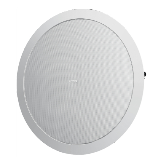
Tannoy CMS801 DC BM Installation Manual

Tannoy CMS801 DC BM Installation Manual

Ceiling monitor systems
Hide thumbs Also See for CMS801 DC BM:

Advertisement

Quick Links

CMS
C E I L I N G M O N I T O R S Y S T E M S
I N S T A L L A T I O N
M A N U A L
CMS801 DC BM
CMS801 DC PI
CMS801 sub BM
CMS801 sub PI
CMS801 PI back can
CMS801 TEMPLATE HOLE CUTOUT SIZE: 295mm (11.61 )

Advertisement

Table of Contents
loading

Summary of Contents for Tannoy CMS801 DC BM

  • Page 1 C E I L I N G M O N I T O R S Y S T E M S I N S T A L L A T I O N M A N U A L CMS801 DC BM CMS801 DC PI CMS801 sub BM...
  • Page 2: Table Of Contents

    MECHANICAL INSTALLATION INSTRUCTIONS FOR OPTIONAL PLASTER RING INSTRUCTIONS FOR PRE-INSTALLATION BACK-CAN (PI MODELS ONLY) WIRING AND SETTING UP DIMENSIONS CMS801 DC BM DIMENSIONS CMS801 DC PI DIMENSIONS CMS801 SUB BM DIMENSIONS CMS801 SUB PI DIMENSIONS CMS801 PI BACK CAN DIMENSIONS...
  • Page 3: Introduction

    When using a power driver to install the product it is essential to use the correct torque level settings to avoid over tightening and damage to the ceiling material or clamps. Recommended torque setting: 1.5Nm Tannoy will not be held responsible for any damages caused by the improper installation of these loudspeakers. ELECTRICAL SAFTEY NOTICE: To comply with the standard UL1480, metal - clad flexible conduit (BX) is required for connection to the terminal block for proper earth grounding.
  • Page 4: Product Feature Identification

    4. PRODUCT FEATURE IDENTIFICATION: Conduit/Cable Clamp Tuning Port Euro Type Connector Screws for mounting wings Mounting Wings Rotary Switch Fig 1.1: The blind-mount (BM) models come with a pre-fitted back can Screws for Tuning Port Euro Type Connector mounting wings Rotary Switch Fig 1.2: A pre-install (PI) model shown without pre-install back can Euro Type Plug...
  • Page 5: Accessories

    5. ACCESSORIES: Each product is supplied with the following accessories as standard: C-Ring Tile bridge kit Note: A tile bridge kit must always be used when installing into suspended ceiling tiles Grille Cut-out template Paint Mask Optional accessories: Plaster (Mud) 60W Transformer Ring NOTE: for use with CMS801 PI...
  • Page 6: Mechanical Installation Guide For Suspended Ceilings

    Slide the speaker assembly through the hole and turn the screws on the front of the speaker to extend the mounting wings. Tighten the screws until a firm grip is achieved. If using a power driver, Tannoy recommends a torque setting of 1.5Nm. DO NOT OVERTIGHTEN! Slide the tile panel back into the suspended ceiling.
  • Page 7: Mechanical Installation Guide For Sheet-Rock Ceilings

    Slide the speaker assembly through the hole and turn the screws to extend the mounting wings. Tighten the screws until a firm grip is achieved. If using a power driver, Tannoy recommends a torque setting of 1.5Nm. DO NOT OVERTIGHTEN!
  • Page 8: Mechanical Installation Instructions For Optional Plaster Ring

    5.3 MECHANICAL INSTALLATION INSTRUCTIONS FOR OPTIONAL PLASTER RING: An optional plaster (mud) ring bracket is available from Tannoy. This bracket is designed to be pre-installed into newly constructed, non-suspended ceilings. Nail or screw the plaster ring to the joists. Lay the speaker wiring to where the speaker will be fitted and complete the plastering work on the ceiling.
  • Page 9: Instructions For Pre-Installation Back-Can (Pi Models Only)

    Slide the speaker assembly through the hole and turn the screws to extend the mounting wings. Tighten the screws until a firm grip is achieved. If using a power driver, Tannoy recommends a torque setting of 1.5Nm. DO NOT OVERTIGHTEN!
  • Page 10: Wiring And Setting Up

    6. WIRING AND SETTING UP: Open the wiring cover at the back of the speaker can to access the Euro type connector plug and socket. For connection to an amplifier, use pins 1 and 2: ¥ Pin 1 is positive ¥...
  • Page 11: Cms801 Dc Bm Dimensions

    7.1 CMS801 DC BM DIMENSIONS: TEMPLATE HOLE CUTOUT SIZE: 295mm 327.8 286.4 310.5 [12.90"] [11.27"] [12.22"] 325.0 [0.20"] [12.80"] 7.2 CMS801 DC PI DIMENSIONS: TEMPLATE HOLE CUTOUT SIZE: 295mm 286.4 [11.27"] 118.7 [4.67"] [0.20"] 325.0 [12.80"] 7.3 CMS801 sub BM DIMENSIONS: TEMPLATE HOLE CUTOUT SIZE: 295mm 286.4...
  • Page 12: Cms801 Sub Pi Dimensions

    7.4 CMS801 sub PI DIMENSIONS: TEMPLATE HOLE CUTOUT SIZE: 295mm 117.5 286.4 [4.63"] [11.27"] 18.5 [0.73"] 325.0 [12.80"] 7.3 CMS801 PI BACK CAN DIMENSIONS: TEMPLATE HOLE CUTOUT SIZE: 295mm 168.5 [6.63"] 397.0 291.4 365.0 [11.47"] [15.63"] [14.37"] 151.2 [0.35"] [5.95"]...
  • Page 13: Technical Specifications

    8.1 TECHNICAL SPECIFICATIONS: MODEL CMS801 DC System Frequency response (-3dB) 47Hz - 30kHz Enclosure BM back can Back can Zinc plated steel Baffle Reflex loaded UL 94V-0 rated ABS Frequency range (-10dB) 40Hz - 35kHz Grille Steel, with weather resistant coating BM back can Safety Features Safety ring located at rear of enclosure...
  • Page 14: Cms801 Sub Specifications

    Tannoy operates a policy of continuous research and development. The introduction of new materials or manufacturing methods will always equal or exceed the published specifications, which Tannoy reserves the right to alter without prior notice. Please verify the latest specifications when dealing with critical applications...
  • Page 15: Painting

    Claims will not be considered if the serial number has been altered or removed. Work under warranty should only be carried out by a Tannoy Professional dealer or service agent. This warranty in no way affects your statutory rights. For further information please contact your dealer or distributor in your country.
  • Page 16: Declaration Of Conformity

    11. DECLARATION OF CONFORMITY: The following apparatus is manufactured in China for Tannoy Ltd of Rosehall Industrial Estate, Coatbridge, Scotland, ML5 4TF and conform(s) to the protection requirements of the European Electromagnetic Compatibility Standards and Directives relevant to Domestic Electrical Equipment. The apparatus is designed...
  • Page 17 NOTES...
  • Page 18 NOTES...
  • Page 19 NOTES...
  • Page 20 Tannoy has a policy of continuous improvement and this specification sheet provides the latest information at the time of printing. All specifications may be subject to further change. Please contact the Tannoy website for the latest information.

Table of Contents