
Related Manuals for Baxi Bermuda Inset 2 Boiler 50/4


Summary of Contents for Baxi Bermuda Inset 2 Boiler 50/4
-
Page 1: Installation And Servicing Instructions
Please leave these instructions with the user Baxi Bermuda Inset 2 Boiler 50/4 Fireside Gas Central Heating Unit Comp N° 238983 - Issue 4 - 10/99 Installation and Servicing Instructions... - Page 2 Everyone who works at the company has a commitment to quality because, as shareholders, we know that satisfied customers mean continued success. We hope you get a satisfactory service from Baxi. If not, please let us know. Baxi is a BS-EN ISO 9001...
-
Page 3: Table Of Contents
Contents - Page 3 Section Page Introduction Technical Data System Details Water Circulating Systems Treatment of Water Circulating Systems Pipework System Controls Fully Pumped System Overheat Kit & Sealed Systems Storage Systems Pumped Heating & Gravity Hot Water Site Requirements Builders Opening Location Fireplace Opening &... -
Page 4: Introduction
Introduction - Page 4 1.1 Description 1. The Baxi Bermuda Inset 2 is a combined central heating boiler and gas fire designed for installation within a builders opening in the living space of a dwelling. 2. The firefront is intended for hearth mounting. -
Page 5: Technical Data
Technical Data - Page 5 Bermuda Inset 2 Boiler 50/4 The Boiler is for use with Natural Gas only. Heat Input Inset 2 50/4 hydraulic resistance 18.79 15.2 Btu/h 64,100 58,070 51,850 Heat Output 14.65 13.19 11.72 Btu/h 50,000 45,000... -
Page 6: System Details
It is important to check the inhibitor concentration after installation, system modification and at every service in accordance with the manufacturer’s instructions. (Test kits are available from inhibitor stockists.) For information or advice regarding any of the above contact the Baxi Helpline. -
Page 7: Pipework
System Details - Page 7 3.3 Pipework 1. The sizes of the flow and return pipes from the boiler should be determined by normal methods according to the requirements of the system. 2. It is recommended that the system is designed for an 11°C (20°... -
Page 8: Overheat Kit & Sealed Systems
(This must not be used on gravity systems.) Baxi Part N° 234885. 2. The boiler can be applied to a sealed system with the use of the overheat kit. -
Page 9: Site Requirements
Site Requirements - Page 9 4.1 Builders Opening (Fig 5) 1. The boiler unit is designed to fit within a standard builders opening, the minimum dimensions of which are as shown. Height 584mm (23in) Width 584mm (23in) Depth 375mm (14¾in) 2. -
Page 10: Flue
Site Requirements - Page 10 4.5 Flue 1. The flue installation must conform to BS 5440 Pt 1. The flue must have a minimum vertical height of 3m (10ft) and have a minimum internal cross section area of 12,700 mm (20in ), this is satisfied by a flue of 125mm (5in) internal diameter. -
Page 11: Ventilation
Site Requirements - Page 11 4.6 Ventilation 1. Ventilation air supply to BS 5440 Pt 2 is required. The permanent ventilation area size requirements are as shown: 80.1cm (12.42in 2. The permanent vent may be directly into the room containing the appliance. The vent may also be sited in another (not a bedroom, toilet, bathroom or kitchen) room provided an interconnecting vent is used. -
Page 12: Installation
Installation - Page 12 5.1 Initial Preparation 1. Remove the outer carton from the boiler pack and locate the fitting kit. Remove and discard the packing pieces. 2. Remove the boiler hood from it’s packing on top of the boiler. The hood may be fitted now or when the boiler is in situ. -
Page 13: Connecting The Sensing Pipe
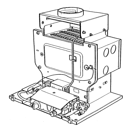
Installation - Page 13 5.3 Connecting the Sensing Pipe 1 Remove the protection cap from the sensing pipe adaptor on the burner mounting plate. Slacken the screw retaining the sensing pipe ‘P’ clip (Fig. 13 & 15). 2. Manoeuvre the pipe so that the flared end aligns with the adaptor. -
Page 14: Water Connections
5.8 Overheat Thermostat 1. For systems requiring an overheat thermostat, an optional kit is available. (Baxi Part N° 234885). The flow pipe arrangement for this type of installation is covered in the instructions supplied with that kit. -
Page 15: Pumped Heating & Gravity Hot Water
Installation - Page 15 5.9 Pumped Heating & Gravity Hot Water (Fig. 18) 1. A 1in x 22mm threaded adaptor, two compression nuts and olives and a brass injector tee piece are provided in the kit for the return connection. NOTE: The injector tee must be fitted to the return of all systems with gravity domestic hot water. -
Page 16: Electrical Connection
Installation - Page 16 5.11 Electrical Connection 1. The appliance requires an electrical supply from the heating controls system. 2. A permanent live supply is required for Deluxe Model Firefronts. WARNING: The appliance must be earthed. The input cable for the appliance should be 0.75mm to lEC Code 227 (heat resistant). -
Page 17: Overheat Thermostat
Installation - Page 17 5.13 Overheat Thermostat 1. Where an overheat thermostat kit is required, the wiring instructions supplied in the kit should be followed. 5.14 Flue Connection (Fig. 25) 1. If not already done so, fit the boiler hood now. Locate the flue within the flue socket and secure with the three self tapping screws provided in the kit. -
Page 18: Commissioning The Appliance
Commissioning the Appliance - Page 18 6.1 Commissioning the Appliance 1. Reference should be made to BS 5449 section 5 when commissioning the boiler and system. Flush the whole system in accordance with BS7593:1992. (See Treatment of Water Circulating Systems section 3.2). Check the system for leaks. -
Page 19: Annual Servicing
Annual Servicing - Page 19 7.1 Annual Servicing 1. To perform annual servicing of the back boiler it is necessary to remove the firefront. 2. After servicing, complete the relevant section of the “Benchmark” Installation, Commissioning and Service Record Log Book. This should be in the possession of the user. -
Page 20: Cleaning The Lint Arrestor
4. The thermocouple cannot be changed as an individual component. The complete assembly must be replaced in the event of one or other component failure(s). 5. Only use a Genuine Baxi Spare Part. 6. Reassemble the burner in reverse order and refit the lint arrestor. -
Page 21: Cleaning The Heat Exchanger
Annual Servicing - Page 21 7.7 Cleaning the Heat Exchanger 1. Remove the top and the centre baffles from the heat exchanger, noting their orientation (Fig. 45). 2. Remove the side and rear insulation pieces by undoing the screws retaining the support brackets and sliding the rear bracket to the left and both side brackets forward (Fig. -
Page 22: Changing Components
Changing Components - Page 22 8.1 Changing Components 1. To change any components on the back boiler it is necessary to remove the fire front. 2. After changing any components carry out gas soundness checks. 8.2 Removal of Firefront 1. Isolate the electrical supply to the appliance. 2. -
Page 23: Thermostat
Changing Components - Page 23 8.5 Thermostat 1. Withdraw the thermostat phial from the boiler door (Fig. 61). 2. Undo the locknut retaining the thermostat to the controls mounting bracket (Fig. 57). Ease the thermostat away from the bracket and disconnect the electrical connections noting their positions. -
Page 24: Gas Valve
Changing Components - Page 24 8.8 Gas Valve 1. Remove the controls cover panel from its retaining clips (Fig. 64). 2. Remove the control knob (Fig. 65). 3. Remove the screw holding the valve cover to the controls mounting bracket and remove the cover (Fig. 65). 4. -
Page 25: Burner & Main Injector
The complete assembly must be replaced in the event of one or other component failure(s). Only use a Genuine Baxi Spare Part. 1. Remove the controls cover panel from its clips if not already done so (Fig. 69). -
Page 26: Fault Finding
Fault Finding - Pages 26 and 27 26 and 27... -
Page 27: Short Parts List
10.0 Short parts list - Page 28 G.C. Description Manufacturers Part No. E01-564 Burner 233904 379 988 Injector B19 234014 E00-121 Ignition Lead 237811 E01-563 Kit Valve 239290 E00-119 Pilot/A.S.D. Assembly 237818 379 999 Thermostat 233952 183 630 Knob Thermostat 042717 183 936 Piezo Igniter Unit...
Need help?
Do you have a question about the Bermuda Inset 2 Boiler 50/4 and is the answer not in the manual?
Questions and answers