Advertisement
Quick Links
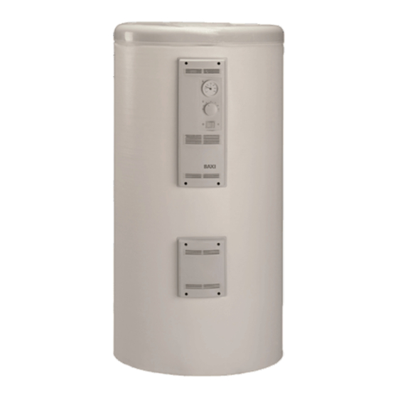
110 E – 150 E
200 E – 300 E – 500 E
ES
Depósitos acumuladores Esmaltados
Instrucciones de Instalación,
Montaje y Funcionamiento para el
INSTALADOR y USUARIO
PT
Depósitos acumuladores Esmaltados
Instruções de Instalação,
Montagem e Funcionamento para o
INSTALADOR e UTENTE
GB
Enamelled storage Cylinders
Installation, Assembly
and Operating Instructions for the
INSTALLER and the USER
Advertisement

Related Manuals for Baxi 500 E


Summarization of Contents
Enamelled Storage Cylinders
Installation and Operation Instructions
Instructions for installers and users covering installation, assembly, and operation.
Dimensions and Technical Characteristics
Cylinder Dimensions and Connections
Tables detailing physical dimensions and connection points for various cylinder models.
Technical Performance Specifications
Key performance data including static losses, efficiency class, capacities, and heat exchange.
Main Components Identification
Component Diagrams and Descriptions
Diagrams and numbered lists identifying all main components and explaining their functions.
Cylinder Main Features and Technical Data
Heat Exchange and Corrosion Protection
Coil heat exchange, enamel coating, and magnesium anodes for corrosion protection.
Optional Electric Heater Functionality
Option to install an electric heater for summer operation without the boiler.
Technical Specifications Summary
Key technical specs: max working pressure and temperature for heating and DHW circuits.
Installation and Water Connections
Mounting and Installation Guidelines
Cylinders for vertical floor-standing or optional vertical wall-mounting.
Hydraulic Connection Recommendations
Advises non-conductive sockets and refers to Appendix 1 for diagrams.
Mandatory Safety Components
Required components for cold water inlet and recommended FLEXBRANE safety unit.
Expansion Vessel for Drip Prevention
Suggests VASOFLEX/S expansion vessel to avoid regular dripping from safety devices.
Electrical Connections and Safety Warnings
Electrical Wiring Procedures
Details power supply, max load, and wiring steps for connecting boilers and cylinders.
Anode Maintenance for Warranty
5-year warranty depends on anode; periodic check via status indicator is essential.
CE Compliance Information
Cylinders comply with Electromagnetic Compatibility and Low Voltage Directives.
Appendix 1: Water Diagrams
Hydraulic Connection Schematics
Diagrams illustrating various hydraulic connections for different boiler and cylinder configurations.
Water Diagrams Legend
Component and Symbol Key
Key to symbols and numbered components used in the hydraulic diagrams.
Appendix 2: Electrical Diagrams
Boiler and Cylinder Wiring Schematics
Diagrams showing electrical connections between specific boiler models and storage cylinders.
Appendix 2: LAIA GT / NGO 50 GT Electrical Diagrams
LAIA GT and NGO 50 GT Wiring Instructions
Specific wiring instructions for connecting LAIA GT (CC-119) and NGO 50 GT (CC-131) boilers.
Appendix 2: LIDIA GT EM Electrical Diagrams
LIDIA GT EM Wiring Instructions
Specific wiring instructions for connecting LIDIA GT EM (CC-159) boiler.
Control Panels and Connection Module
MC-200 Module Connection Procedures
Steps for connecting the MC-200 module to boiler and cylinder control systems.
Electrical Wiring and Component Connections
Details on connecting DHW pump, cylinder terminals, electric heater, and wiring harnesses.
Thermostat Installation Notes
Instructions for installing TA-200/RA-200 thermostats, including jumper removal.
Electrical and Water Diagram Legends
Symbol and Component Key
Explanation of symbols and components used across electrical and hydraulic diagrams.
Need help?
Do you have a question about the 500 E and is the answer not in the manual?
Questions and answers