
Related Manuals for Potterton Performa System 12e


Summary of Contents for Potterton Performa System 12e
- Page 1 Performa System 12e, 18e, 24e & 28e Gas Fired Wall Mounted System Boilers Installation and Servicing Instructions Please leave these instructions with the user...
- Page 2 Natural Gas Potterton Performa System 12e G.C.N 41 590 88 Potterton Performa System 18e G.C.N 41 590 89 Potterton Performa System 24e G.C.N 41 590 90 The boiler meets the requirements of Statutory Potterton Performa System 28e G.C.N 41 590 91 Instrument “...
-
Page 3: Table Of Contents
Contents Section Page Introduction General Layout Appliance Operation Technical Data Dimensions and Fixings System Details Site Requirements Installation Commissioning the Boiler 10.0 Completion 11.0 Servicing the Boiler 12.0 Changing Components 13.0 Illustrated Wiring Diagram 14.0 Fault Finding 15.0 Short Parts List 16.0 Notes... -
Page 4: Introduction
“Benchmark” Log Book Undertaking. Where no specific instructions are given, reference should be made to the relevant As part of the industry-wide “Benchmark” initiative all Potterton boilers now BRITISH STANDARD CODES OF PRACTICE. include an Installation, Commissioning and Service Record Log Book. -
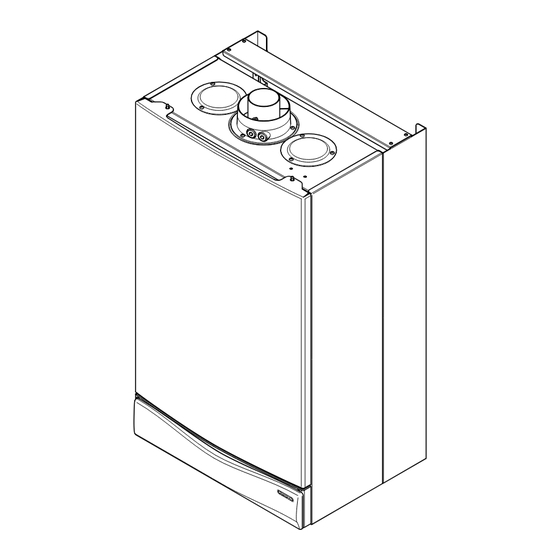
Page 5: General Layout
2.0 General Layout Layout Air Pressure Switch Expansion Vessel Burner Manifold Automatic Air Vent Circulation Pump Drain Off Point Pressure Relief Valve Optional Integral Timer Position System Pressure Gauge Control Box Spark Generator Flame Sensing Electrode Spark Electrode Burner Primary Heat Exchanger Fan Assembly On/Off/Reset Selector Switch Central Heating Temperature Control... -
Page 6: Appliance Operation
3.0 Appliance Operation Boiler Primary Circuit Operating Mode (Fig. 2) 1. With a demand for heating, the pump circulates water through the primary circuit. At a pre- determined flow rate the hydraulic differential pressure switch operates, initiating the ignition sequence. 2. -
Page 7: Technical Data
4.0 Technical Data System 12e Appliance Type Pump - Grundfos UP 15-50 NO x Class Available Head See graph below Appliance Category CAT II Flue Terminal Diameter 100mm 2H 3+ Expansion Vessel - (For Central Heating Dimensions Projection 95mm Heat Input (Gross) only. - Page 8 4.0 Technical Data System 18e Appliance Type Pump - Grundfos UP 15-50 NO x Class Available Head See graph below Appliance Category CAT II Flue Terminal Diameter 100mm 2H 3+ Expansion Vessel - (For Central Heating Dimensions Projection 95mm Heat Input (Gross) only.
- Page 9 4.0 Technical Data System 24e Appliance Type Pump - Grundfos UP 15-50 NO x Class Available Head See graph below Appliance Category CAT II Flue Terminal Diameter 100mm 2H 3+ Expansion Vessel - (For Central Heating Dimensions Projection 95mm Heat Input (Gross) only.
- Page 10 4.0 Technical Data System 28e Appliance Type Pump - Grundfos UP 15-60 NO x Class Available Head See graph below Appliance Category CAT II Flue Terminal Diameter 100mm 2H 3P Expansion Vessel - (For Central Heating Dimensions Projection 95mm Heat Input (Gross) only.
-
Page 11: Dimensions And Fixings
5.0 Dimensions and Fixings Dimensions A 780mm B 345mm C 450mm D 107mm Ø Min. E 200mm F 190mm G 143mm 360° Orientation Tube Ø 100mm Tap Rail 130 mm 130 mm 65 mm Heating Heating Pressure Relief Return Valve Flow Inlet (22mm) -
Page 12: System Details
(Test kits are available from inhibitor stockists.) • For information or advice regarding any of the above contact the Potterton Helpline. Bypass 1. The boiler is fitted with an automatic integral bypass. System Control 1. - Page 13 6.0 System Details System Filling and Pressurising 1. A filling point connection on the central heating return pipework must be provided to facilitate initial filling and pressurising and also any subsequent water loss replacement/refilling. Double Stop Check Stop 2. The filling method adopted must be in Valve Valve Valve...
-
Page 14: Site Requirements
7.0 Site Requirements 450mm 5mm Min 5mm Min Information 1. The installation must be carried out by a CORGI Registered Installer or other registered competent person and be in accordance with the relevant 200mm Min requirements of the current G (Installation AFETY and Use) R... - Page 15 7.0 Site Requirements Ventilation of Compartments 1. Where the appliance is installed in a cupboard or compartment, no air vents are required. 2. BS 5440: Part 2 refers to room sealed appliances installed in compartments. The appliance will run sufficiently cool without ventilation.
- Page 16 7.0 Site Requirements Flue 1. The flue terminal position must be in accordance with the current editions of B.S. 5440 Part 1, and either Part J of the Building Regulations England and Wales or Part F of the Building Standards (Scotland) Regulations as appropriate.
- Page 17 7.0 Site Requirements Flue Dimensions The standard horizontal flue kit allows for flue lengths between 100mm and 1m from elbow to terminal (Fig. 10). The maximum permissible equivalent flue length is: System 12e,18e,24e 5 metres System 28e 4 metres Fig. 10 7.10 Flue Terminal Trim 1.
- Page 18 7.0 Site Requirements 7.12 Flue Options 1. The Potterton Performa System can be fitted with flue systems as illustrated. 2. The standard flue is suitable only for horizontal applications. Maximum Length = 3m (28e) 4m (12e,18e,24e) 3. Maximum permissible equivalent flue lengths inc.
-
Page 19: Installation
NOTE: A small amount of water may drain from the boiler in the upright position. Central Heating Return Potterton declare that no substances harmful to health are contained in the Fig. 15 appliance or used during appliance... - Page 20 Wall Plate 8.0 Installation Fitting The Boiler 1. Remove the sealing caps from the boiler connections. 2. Lift the boiler using the lower edges. Engage the slots at the top rear of the boiler on the wall plate (Fig. 16). 3.
- Page 21 8.0 Installation Wall Thickness Fitting The Flue HORIZONTAL FLUE 1. The standard flue is suitable for lengths 100mm minimum to 1m maximum (measured from the edge of the flue elbow outlet). Rear Flue: maximum wall thickness - 900mm Side Flue: maximum wall thickness - 870mm 2.
- Page 22 8.0 Installation Elbow Fitting the Flue (Cont) IMPORTANT: If the equivalent flue length is Seal greater than 1.5m the restrictor MUST be Restrictor removed from the adaptor (Fig. 20). Adaptor 8. Take one of the rubber seals and position it on Fig.
- Page 23 8.0 Installation Making The Electrical Connections To connect the mains input cable proceed as follows:- 1. Slacken the facia securing screws and lift the outercase panel so that its securing tabs are clear of the facia. Remove the panel. Control Box Cover 2.
-
Page 24: Commissioning The Boiler
Commissioning the Boiler Commissioning the Boiler Screw 1. Reference should be made to BS 5449 when commissioning the boiler. 2. Ensure that the filling loop is connected and Automatic open, then open the heating flow and return Air Vent valves on the boiler. 3. - Page 25 Commissioning the Boiler Pressure Test Point Sealing Screw Checking the Burner Pressure 1. Turn on the gas and electrical supplies to the boiler and ensure that all external controls are Gas Valve calling for heat. 2. Set the temperature control to maximum and the selector switch to the Off position (Fig.
-
Page 26: Completion
10.0 Completion 10.1 Completion Case Front Panel 1. Hinge the facia panel upwards and refit the case front panel. Secure them with the screws previously removed (Fig. 37). 2. Instruct the user in the operation of the boiler and system, explaining the operational sequence. 3. -
Page 27: Servicing The Boiler
11.0 Servicing the Boiler Case Front Panel 11 .1 Annual Servicing 1. For reasons of safety and economy, it is recommended that the boiler is serviced annually. Servicing must be performed by a competent person. 2. After servicing, complete the relevant section of the “Benchmark”... - Page 28 Baffle 11.0 Servicing the Boiler Spring Clip 11.1 Annual Servicing (Cont) 11. Remove the spring clips retaining the air box side baffle plates. Disengage the tabs on the baffles from the slots in the fan hood (Fig. 41). 12. Undo the screws securing the fan and hood to the appliance back panel.
-
Page 29: Changing Components
12.0 Changing Components IMPORTANT: When changing components Pressure ensure that both the gas and electrical Switch supplies to the boiler are isolated before any work is started. When the new component has been fitted turn the selector switch fully anticlockwise against the spring pressure to Sensing position R and hold for 2 seconds to reset the Tubes... - Page 30 12.0 Changing Components 12.3 Heat Exchanger (Fig. 47) Heat Exchanger 1. Note the positions of the two sensing tubes on (12e, 18e, 24e model) the outlet elbow and three wires on the fan motor and remove them. 2. Slacken the screws on the outlet sealing collar. Ease the collar upwards as far as possible.
- Page 31 12.0 Changing Components Injector Inlet Elbow Manifold 12.5 Injectors (Fig. 49) 1. Remove the burner as described in Section 12.4. 2. Undo the screws securing the injector Gasket manifold to the inlet elbow and remove the manifold. 3. Unscrew and replace injectors as required Injector and examine the sealing gasket, replacing as necessary.
- Page 32 12.0 Changing Components 12.8 Gas Valve (Fig. 51) 1. Undo the nut on the gas feed pipe under the Gas Valve boiler. Modulator 2. Remove the securing screws and hinge the Wires facia panel down. 3. Disconnect the earth wire and pressure sensing pipe from the valve.
- Page 33 12.0 Changing Components 12.12 Pump - Head Only (Fig. 54) 1. Drain the primary circuit and remove the socket head screws securing the pump head to the body and draw the head away. 2. Undo the screw on the pump wiring cover and remove the cover.
- Page 34 12.0 Changing Components Pressure Gauge Capillary 12.15 Pressure Gauge (Figs. 57 & 58) 1. Drain the primary circuit and undo the nut on the pressure gauge capillary. 2. Remove the timer cover and ease the timer wiring aside. Undo the screws securing the gauge retaining bracket.
- Page 35 12.0 Changing Components 12.18 Main PCB (Fig. 62) 1. Note the setting of the temperature control knob. Rotate the knob fully anticlockwise and carefully pull it off the drive pin. 2. Remove the screws securing the control box cover and release the cover retaining barbs from their slots.
- Page 36 12.0 Changing Components 12.20 Central Heating Differential Valve (Figs. 63 & 64) 1. Drain the primary circuit. 2. Undo the screw securing the microswitch to the differential valve. Allow the microswitch to rest to one side. 3. Undo the pressure gauge capillary nut and heating flow pipe nut from the valve.
-
Page 37: Illustrated Wiring Diagram
13.0 Illustrated Wiring Diagram Pump Air Pressure Switch Hydraulic Differential Pressure Switch Control PCB Return Heating Temperature Sensor Flame Sensing Central Heating Electrode NTC Sensor Mains Input - brown Link - black - blue - red - green - green / yellow Fuse - white Overheat Stat... -
Page 38: Fault Finding
14.0 Fault Finding Carry out initial fault finding checks 1. Check that gas, water and electrical supplies are available at the boiler. Electrical supply = 230V ~ 50 Hz. CH water system pressurised to 0.5 bar when the boiler is cold. The preferred minimum gas pressure is 19.5mbar (natural gas), 27mbar (butane) or 36mbar (propane). - Page 39 14.0 Fault Finding Fault Finding Solutions Sections A to E Is there 230V at: Main terminals L and N Check electrical supply Main terminal fuse Replace fuse neon Replace PCB illuminated Selector terminals a & b Check wiring and a & 3. PCB - A4 Replace selector connector terminals 4 &...
- Page 40 14.0 Fault Finding Check the burner setting pressure of the gas valve (see Section 9.2 of Commissioning) Voltage at modulating coil of gas valve is: Max. burner press.approx 9V DC (13V DC LPG) Replace gas valve Min. burner press.approx 1V DC Current at modulating coil of gas valve is: (Use an instrument with average function for this measure)
-
Page 41: Short Parts List
15.0 Short Parts List Short Parts List Key G.C. Description Manufacturers No. No. Part No. E66 383 Fan 12e,18e, 24e 248001 E66 527 Fan 28e 248002 393 374 Pressure Switch 247380 E66 393 Heat Exchanger 12e,18e, 24e 248016 E66 535 Heat Exchanger 28e 248017 E66 398... -
Page 42: Notes
16.0 Notes... - Page 43 16.0 Notes...
- Page 44 Potterton, Baxi UK Limited, Brownedge Road, Bamber Bridge, Preston, Lancashire. PR5 6SN After Sales Service 08706 096 096 Technical Enquiries 08706 049 049 www.baxi.com 922.516.1 Comp N 5107333 - Iss 1 - 6/02...
Need help?
Do you have a question about the Performa System 12e and is the answer not in the manual?
Questions and answers