Table of Contents
Advertisement
Quick Links
harman/kardon
A/V DOLBY DIGITAL RECEIVER
LEAKAGE TEST.................................................. 3
SPECIFICATIONS................................................4
CONTROLS AND FUNCTIONS...............................6
REAR PANEL CONNECTIONS...............................8
SERVICE PROCEDURE........................................9
ALIGNMENT PROCEDURES..................................9
MAIN AMP IDLING CURRENT ADJUSTMENT.........10
ALIGNMENT AND TEST POINTS.......................... 11
CIRCUIT DESCRIPTION ......................................13
BLOCK DIAGRAM.............................................. 16
DISASSEMBLY PROCEDURES ............................17
GENERAL UNIT PARTS LIST................................18
GENERAL UNIT EXPLODED VIEW........................20
SERVICE BULLETIN HK9804................................21
AVR45
SERVICE MANUAL
harman/kardon, Inc.
250 Crossways Park Dr.
Woodbury, New York 11797
CONTENTS
SERVICE BULLETIN HK9903............................22
SERVICE BULLETIN HK2000-01........................23
SERVICE BULLETIN HK2001-02........................25
PC . BOARDS.................................................27
ELECTRICAL PARTS LIST ...............................32
IC BLOCK DIAGRAMS ....................................48
CPU BLOCK DIAGRAM....................................59
DISPLAY SEGMENTS......................................67
FLT PIN CONFIGURATION ..............................68
SCHEMATIC DIAGRAMS..................................69
SCHEMATIC DIAGRAMS (RDS/SG)...................76
SEMICONDUCTOR PIN DIAGRAM.....................85
WIRING DIAGRAM ..........................................86
PACKING MATERIAL AND PARTS LIST ..............87
Rev1 - 8/2005
Advertisement
Table of Contents

Related Manuals for Harman Kardon AVR45


Summary of Contents for Harman Kardon AVR45
-
Page 1: Table Of Contents
AVR45 A/V DOLBY DIGITAL RECEIVER SERVICE MANUAL CONTENTS ELECTROSTATICALLY SENSITIVE(ES)DEVICES..…2 SERVICE BULLETIN HK9903……………………….22 LEAKAGE TEST……………………….…………………. 3 SERVICE BULLETIN HK2000-01………….……..…23 SPECIFICATIONS…………………………………………4 SERVICE BULLETIN HK2001-02………….……..…25 CONTROLS AND FUNCTIONS………………………….6 PC . BOARDS……………………………………..…..27 REAR PANEL CONNECTIONS………………………….8 ELECTRICAL PARTS LIST ……………………..…..32 SERVICE PROCEDURE…………………………..……..9 IC BLOCK DIAGRAMS ……………………….……..48 ALIGNMENT PROCEDURES………….…………..…….9... -
Page 2: Electrostatically Sensitive(Es)Devices
Some semiconductor (solid state) devices can be damaged easily by static electricity. Such components commonly are called Electrostatically Sensitive (ES) Devices. Examples of typical ES devices are integrated circuits and some field effect transistors and semiconductor "chip" components. The following techniques should be used to help reduce the incidence of component damage caused by static electricity. 1. -
Page 3: Leakage Test
Before returning the unit to the user, perform the following safety checks : 1 Inspect all lead dress to make certain that leads are not pinched or that hardware is not lodged between the chassis and other metal parts in the unit. 2. -
Page 4: Specifications
RMS Output Power THD(0.5%, 8 ohms, 1kHz) All Channel Driven S/N Ratio(Input Level : 200mV) Input Shorted, IHF-A WTD 65dB 60dB Nominal Limit Frequency Respones at-3dB Continuous Power Output 8 ohms, Dolby Pro Logic 100Hz-20kHz 150Hz-20kHz (STEREO MODE), Input : CD THD : 0.08%, 8 ohms Both Channel Driven(20Hz-20kHz) (SURROUND MODE) - Page 5 Tuning Cover Range 50 kHz Step for AVR-45RDS/SG Image Rejection(at 999kHz) 40dB IF Rejection(at 999/1000kHz) 50dB Mono Usable Sensitivity(75 ohms Input, 98MHz) AGC Figure of Merit(From 100mV/m at 999/1000kHz) 14.2dbf 17.2dbf 50dB Image Rejection(at 98MHz) Distortion(999/1000kHz, 30% MOD, 50mV/m Input) 80dB 1.0% IF Rejection(at 90MHz)
-
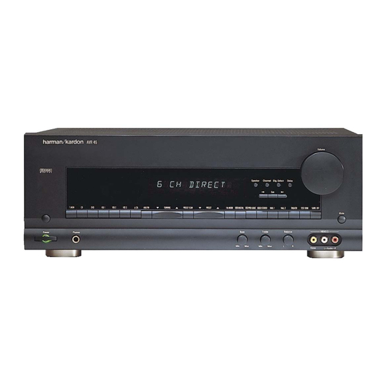
Page 6: Controls And Functions
CONTROLS AND FUNCTIONS stations. When a station with a strong signal is program that carries the Dolby Digital information. Delay : Press this button to begin the Front Panel tuned, the TUNED indicator will illuminate in sequence of steps required to enter delay time the Information Display . - Page 7 Remote Control select a surround mode. Numeric Keys : These buttons serve as a indicator to enter your choice. To change the surround mode, first press the ten-button numeric key-pad to enter tuner preset SURR/CH button . Next press these positions.
-
Page 8: Rear Panel Connections
Main Information Display : This display DVD Inputs : Connect the analog audio the "IR IN" jack on Harman Kardon or other Optical Digital input indicates the station preset number that is shows messages relating to the status, input outputs and composite video output of a DVD or... -
Page 9: Service Procedure
TEST EQUIPMENT REQUIRED 1. All Clear 1) AM/FM Signal generator This service program can clear all memorized operations and functions. When the POWER ON, press the "AM/FM" button while pressing the "PRO LOGIC"button. 2) Digital Multimeter After this, Preset memory will be set to these frequencies. 3) Distortion lever meter VERSION 87.5... -
Page 10: Main Amp Idling Current Adjustment
4. AM OSC Adujstment 8. Main Amp ldling current Adjustment Signal Reception Input Signal Source Source Signal Output Level and Adjustment Adjustment 1) Alignment condition step Frequency Frequency Connection Modulation Point Value (1) Adjust each of the variable resistors below in both the main and surround boards to the center position : 522kHz MAIN AMP BOARD : VR401, VR402, VR501 Signal Generator... -
Page 17: Disassembly Procedures
DISASSEMBLY PROCEDURE DISASSEMBLY PROCEDURE 1. Removing the top cover, and 4. Removing the main PCB block, and Remove screws Remove screws 2. Removing the front panel, and 5. Removing the power PCB block, and Remove screws Remove 3. Removing the rear panel, and 6. -
Page 18: General Unit Parts List
GENERAL UNIT PARTS LIST REF NO. REF NO. PART NO. PART NO. DESCRIPTION Q'TY 5111-005-010 PANEL. FRONT 5111-008-010 PANEL. FRONT 5131-003-010 KNOB. FUNCTION (A) 5131-003-020 KNOB. FUNCTION (B) 5131-003-030 KNOB. FUNCTION (C) 5131-003-040 KNOB. POWER 5131-003-050 KNOB. PUSH 5131-003-060 KNOB. TACT 5131-003-070 KNOB. - Page 19 UNIT PARTS LIST REF NO. REF NO. PART NO. PART NO. DESCRIPTION Q'TY 39-B A0191-075-001 REMO CON ASSY AB 5636-140-010 SCREW 3*10 TEETH COPPER 5636-140-040 SCREW A183008000 5636-140-060 SCREW S30C BTTN D12.3X10 MC 5636-140-100 SCREW A123008002 5636-140-050 SCREW A183006002 5636-140-220 SCREW A183006002 5636-140-080 SCREW A124008000...
-
Page 21: Service Bulletin Hk9804
A: AVR35 − Press the TV and the M4 buttons at the same time and hold for 12 seconds. B: AVR45 or AVR65 − Press the TV and the LIGHT buttons at the same time and hold for 12 seconds. -
Page 22: Service Bulletin Hk9903
Digital products such as newer FAX machines and state of the art audio products like the AVR35, AVR45 and AVR65 often produce more RF interference than traditional analogue designs. -
Page 23: Service Bulletin Hk2000-01
Subject: No Output in Surround Modes In early versions of the AVR35, AVR45 and AVR65, the IC484 +5v regulator may overheat and go into thermal protection. Its +5 volt output will cease; when this happens the AC-3 and Surround Processor cannot function normally, and the audio output may go dead, or experience a long delay before any surround mode comes on. - Page 24 AVR45 harman/kardon Models: AVR35/AVR45/AVR65 Subject: No Output in Digital Playback Mode Model Serial number Serial number Status Action 120V 230V RDS JS0007-01000 JS0005-01000 AVR35 Replace R486 and R495 with (2) 15 ohm IC484 Overheating; JS0007-14748 JS0005-05956 3 watt resistors, soldered in series to Unit’s output ceases and “No...
-
Page 25: Service Bulletin Hk2001-02
AVR45 harman/kardon harman/kardon Service Bulletin Service bulletin # HK2001-02 June 2001 Warranty labor rate: MAJOR repair To: All harman/kardon Service Centers Models: AVR35/45/65, (US,SG,RDS Models) Subject: Left, Right, or Center channel Dead In the event you receive an AVR35, 45, or 65 A/V receiver with the complaint: “One channel has no output”, check the item below:... - Page 26 AVR45 harman/kardon...
-
Page 32: Electrical Parts List
REF NO. PART NO DESCRIPTION REF NO. PART NO DESCRIPTION Q 432 1244-124-002 KTA1024-Y 0112-011-150 MAIN AMP P .C.BOARD Q 509 1244-124-002 KTA1024-Y Q 511 1244-124-002 KTA1024-Y INTEGRATED CIRCUITS Q 516 1244-124-002 KTA1024-Y Q 557 1244-126-004 KTA1266-GR IC 481 1217-781-001 7815 REGULATOR KTA1266-GR... - Page 33 REF NO. PART NO DESCRIPTION REF NO. PART NO DESCRIPTION 1744-152-731 1/8W 10KW-J R 504 1/4W 1.5KW-J R 580 1742-103-721 1744-153-731 1/8W 10KW-J R 437 1/4W 15KW-J R 591 1742-103-721 1/8W 10KW-J R 438 1744-153-731 R 479 1742-103-721 1/4W 15KW-J 1/8W 10KW-J R 439...
- Page 34 REF NO. PART NO DESCRIPTION REF NO. PART NO DESCRIPTION R 427 1761-561-731 1/4W 560W-J C 482 1861-822-214 ELECT 8200uF-M R 428 1761-561-731 1/4W 560W-J C 561 1862-010-804 ELECT 1.0uF-M R 429 1761-561-731 1862-100-017 1/4W 560W-J C 413 ELECT 100V 10uF-M R 430 1761-561-731...
- Page 35 REF NO. PART NO DESCRIPTION REF NO. PART NO DESCRIPTION WA 413 2114-604-009 JE-604-09,PLUG Q 618 1244-124-002 KTA1024-Y 2114-604-010 WA 407 JE-604-10,PLUG Q 621 1244-124-002 KTA1024-Y 2114-604-010 WA 421 JE-604-10,PLUG Q 622 1244-124-002 KTA1024-Y WA 414 2114-604-011 JE-604-11,PLUG 1244-124-002 Q 631 KTA1024-Y WA 417 2114-604-011...
- Page 36 REF NO. PART NO DESCRIPTION REF NO. PART NO DESCRIPTION R 620 1744-202-731 1/4W 2KW-J C 691 1861-682-800 ELECT 50V 6800uF-M 1744-331-731 R 609 1/4W 330W-J C 692 1861-682-800 ELECT 50V 6800uF-M R 610 1744-331-731 1862-100-017 1/4W 330W-J C 613 ELECT 100V 10uF-M...
- Page 37 REF NO. PART NO DESCRIPTION REF NO. PART NO DESCRIPTION R 982 1744-222-731 1/4W 2.2KW-J Q 112 1243-101-018 KRC101M 1/4W 560W-J Q 116 1243-101-018 KRC101M R 987 1744-561-731 R 993 1742-682-721 1/8W 6.8KW-J Q 117 1243-101-018 KRC101M 1243-130-003 Q 101 KTD1302 RESISTORS(FUSIBLE) Q 102...
- Page 38 REF NO. PART NO DESCRIPTION REF NO. PART NO DESCRIPTION R 254 1742-102-721 1/8W 1KW-J R 256 1742-224-721 1/8W 220KW-J 1742-102-721 1742-224-721 R 267 1/8W 1KW-J R 147 1/8W 220KW-J 1742-822-721 R 148 1742-224-721 R 227 1/8W 8.2KW-J 1/8W 220KW-J R 228 1742-822-721 R 151...
- Page 39 REF NO. PART NO DESCRIPTION REF NO. PART NO DESCRIPTION C 137 1862-4R7-804 ELECT 4.7uF-M CAPACITORS 1862-4R7-804 C 138 ELECT 4.7uF-M 1862-4R7-804 C 199 1832-104-002 CERA/AX 0.1uF-Z C 145 ELECT 4.7uF-M C 146 1862-4R7-804 ELECT 4.7uF-M C 200 1832-104-002 CERA/AX 0.1uF-Z C 203 1832-104-002...
- Page 40 REF NO. PART NO DESCRIPTION REF NO. PART NO DESCRIPTION Q 914 1243-319-007 KTC3199-GR R 956 1742-392-721 1/8W 3.9KW-J Q 915 1243-319-007 KTC3199-GR R 901 1742-471-721 1/8W 470W-J 1243-319-007 1742-473-721 Q 916 KTC3199-GR R 914 1/8W 47KW-J 1243-319-007 R 915 1742-473-721 Q 917 KTC3199-GR...
- Page 41 REF NO. PART NO DESCRIPTION REF NO. PART NO DESCRIPTION C 961 1862-220-804 ELECT 22uF-M SW 926 1671-000-020 SW-TACT SKHV10910A,2P C 962 1862-220-804 ELECT 22uF-M SW 927 1671-000-020 SW-TACT SKHV10910A,2P 1879-823-712 1671-000-020 C 939 FILM 100V 0.082uF-J SW 928 SW-TACT SKHV10910A,2P 1879-823-712 FILM...
- Page 42 REF NO. PART NO DESCRIPTION REF NO. PART NO DESCRIPTION Q 715 1243-130-003 KTD1302 R 729 1746-101-771 1/10 100W-J 1746-101-771 R 730 1/10 100W-J DIODE 1746-101-771 R 731 1/10 100W-J D 01 1252-000-017 1SS133 , SW. R 732 1746-101-771 1/10 100W-J R 741 1746-101-771...
- Page 43 REF NO. PART NO DESCRIPTION REF NO. PART NO DESCRIPTION R 760 1746-302-771 1/10 3KW-J C 727 1846-222-882 CERA 0.0022uF-K 1746-302-771 R 773 1/10 3KW-J C 728 1846-222-882 CERA 0.0022uF-K R 774 1746-302-771 1/10 3KW-J C 731 1846-222-882 CERA 0.0022uF-K R 711 1746-473-771 1/10...
- Page 44 REF NO. PART NO DESCRIPTION REF NO. PART NO DESCRIPTION C 713 1862-4R7-804 ELECT 4.7uF-M RD 10 1746-224-771 1/10W 220KW-J 1746-224-771 C 714 1862-4R7-804 ELECT 4.7uF-M RD 15 1/10W 220KW-J 1862-4R7-804 1746-224-771 C 717 ELECT 4.7uF-M RD 16 1/10W 220KW-J 1862-4R7-804 RD 21 1746-224-771...
- Page 45 REF NO. PART NO DESCRIPTION REF NO. PART NO DESCRIPTION CD 6 1862-4R7-804 ELECT 4.7uF-M R 361 1742-102-721 1/8W 1KW-J CD 7 1862-4R7-804 ELECT 4.7uF-M R 362 1742-102-721 1/8W 1KW-J 1862-4R7-804 CD 8 ELECT 4.7uF-M R 363 1742-102-721 1/8W 1KW-J CD 11 1862-4R7-804 ELECT...
- Page 46 REF NO. PART NO DESCRIPTION REF NO. PART NO DESCRIPTION R 861 1742-103-721 1/8W 10KW-J INTEGRATED CIRCUITS R 862 1742-103-721 1/8W 10KW-J 1212-126-002 1742-103-721 IC 801 R 893 1/8W 10KW-J LA1266 AM/FM IF IC 803 1212-341-001 R 814 1742-104-721 1/8W 100KW-J LA3410 FM MPX...
- Page 47 REF NO. PART NO DESCRIPTION CT 801 1815-020-001 C-TRIM 20pF CAPACITORS C 855 1822-150-712 CERA/RA 15pF-J C 844 1822-300-712 CERA/RA 30pF-J 1822-300-712 C 845 CERA/RA 30pF-J 1822-330-712 C 814 CERA/RA 33pF-J C 815 1822-330-712 CERA/RA 33pF-J C 891 1822-331-712 CERA/RA 33pF-J C 838 1822-331-712...
-
Page 59: Cpu Block Diagram
AVR45 harman/kardon... -
Page 67: Display Segments
AVR45 harman/kardon... -
Page 68: Flt Pin Configuration
AVR45 harman/kardon TYPE: CM1684C ANODE & GRID ASIGNMENT THEATER MPEG HALL 2 HALL 1 3-STEREO PLO LOGIC DIGITAL DISPLAY NIGHT MULTI TUNED MONO STEREO AUTO MEMORY VMAX PRESET SLEEP MUTE BYPASS ALALOG COAX AC-3 PIN ASSIGNMENT Pin No. 19 33 Assignment Pin No. -
Page 69: Schematic Diagrams
FRONT...
Need help?
Do you have a question about the AVR45 and is the answer not in the manual?
Questions and answers