Table of Contents
Advertisement
Quick Links
Advertisement
Table of Contents

Related Manuals for Russell Hobbs RHFZ1


Summary of Contents for Russell Hobbs RHFZ1
-
Page 3: Technical Specifications
TECHNICAL SPECIFICATIONS Supplier's nam e or trade mark RUSSELL HOBBS Model / Item RHFZ1 Type of appliance GT/N390P The energy efficiency class Voltage 220-240V / 50HZ Power 1,2A Energy consumption 1,020kwh/24h Gross storage volume of frozen food 286 lt. Net storage volume of frozen food 265 lt. -
Page 4: Table Of Contents
Index TECHNICAL SPECIFICATIONS ................1 BEFORE USING THE APPLIANCE ..............3 Safety instructions ......................3 Safety warnings ........................3 Before Switching On ......................4 Installing and operating your freezer ................5 THE PARTS OF THE APPLIANCE AND THE COMPARTMENTS ......6 THE VARIOUS FUNCTIONS AND POSSIBILITIES .......... -
Page 5: Before Using The Appliance
BEFORE USING THE APPLIANCE Safety instructions • If the model contains R600a-see name plate under refrigerant (the coolant isobutane), naturals gas that, is very environmentally friendly but also combustible. W hen transporting and installing the unit care must be taken to ensure that none of the refrigeration circuit components become damaged. -
Page 6: Before Switching On
• This appliance is designed for use by adults, do not allow children to play with the appliance or let them to hang over the door. • Do not plug-in or pull out the plug from the plug socket with wet hands to prevent electrocution! •... -
Page 7: Installing And Operating Your Freezer
Installing and operating your freezer • Before making the connection to the power supply, ensure that the voltage on the nameplate corresponds to the voltage of electrical system at your home. • Operating voltage for your freezer is 220-240 V at 50Hz. •... -
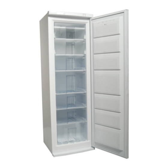
Page 8: The Parts Of The Appliance And The Compartments
THE PARTS OF THE APPLIANCE AND THE COMPARTMENTS Parts may vary according to the appliance model. 1. ICE TRAY 5. FREEZER BIG DRAWER 2. DISPLAY PANEL 6. FREEZER DRAWERS 3. FREEZER THERMOSTAT DIAL 7. FREEZER BOTTOM DRAWER 4. FREEZER FLAPS 8. -
Page 9: The Various Functions And Possibilities
THE VARIOUS FUNCTIONS AND POSSIBILITIES Thermostat setting FREEZER THERMOSTAT Freezer control Freezer thermostat automatically regulates the inside temperature of the compartments. By rotating the knob from position “1” to “5”, colder temperatures can be obtained. Freezer thermostat setting; : This position shows thermostat is closed and no cooling is available. 1 –... -
Page 10: Display Panel
Display panel Orange Lamp Green Lamp Red Lamp W hen the “Super Freezing” operation is on (thermostat dial is in SF ORANGE LAMP: position), the orange lamp will turn on. When the appliance is connected to the power supply, the green lamp GREEN LAMP: on the display panel will turn on automatically. -
Page 11: Food Storage
FOOD STORAGE • Do not put fresh and warm food with frozen food side by side as it can thaw the frozen food. • While freezing fresh food (i.e. meat, fish and mincemeat) divide them to partions in order to use individually. •... -
Page 12: Cleaning And Maintenance
CLEANING AND MAINTENANCE • Disconnect unit from the power supply before cleaning. • Do not clean the appliance by using encessive amounts of water. • The freezer compartment should be cleaned periodically using a solution of bicarbonate of soda and lukewarm water. •... -
Page 13: Defrosting
Defrosting WARNING: Never use sharp metal tools, unless recommended by manufacturer, for this operation as they can damage the freezing circuit. After a period of time, frost will build up in certain areas in the freezer compartment. The frost, accumulated in the freezer compartment, should be removed periodically (use the plastic scraper if available). -
Page 14: Changing The Door Swing Direction To Right Hand
CHANGING THE DOOR SWING DIRECTION TO RIGHT HAND 1- Remove the kick plate by pulling forward. 2- Unscrew the bottom hinge fixing screws (Fig-1) and remove it (Fig-2) Figure 1 Figure 2 3- Dismantle the door from the top hinge by pulling the door downwards. 4- Unscrew the pin of the right top hinge. - Page 15 7- Replace the door top bushing (Fig-6) and top bushing cap. (Fig-7) Figure 6 Figure 7 8- Remove the door bottom bushing and 9- Remove the door bottom bushing and bottom stopper and then insert them the left insert it into left hole. (Fig-9) side.
- Page 16 11- Assemble the door together with bottom 12- Finally,by using a knife cut left side of hinge. Then screw the hinge to bottom left the kick plate and assemble it. (Fig-12) side of refrigerator. (Fig-11) Knife cut Figure 11 Figure 12 For Customer Services, Spare Parts &...
-
Page 17: Assembly Instruction (Freezer-Larder)
ASSEMBLY INSTRUCTION FREEZER - LARDER Side By Side For Customer Services, Spare Parts & Warranty Information please call 0845 683 8717 - 15 -... - Page 18 Part list 1) Flat metal kit; 2 pcs. 2) Bent metal kit; 2 pcs. 3) Gasket; 1 pc. 4) Flat screw (M4); 2 pcs. 5) Conic screw; 4 pcs. 6) Flat screw; 2 pcs. 7) Fixing bracket front; OPTIONAL 8) Adjustable feed Must be ordered as a spare part.
- Page 19 Fig. C Fig. B Fig. A - 7 - Adjustable feet h pdfFactory Pro trial version www.pdffactory.com For Customer Services, Spare Parts & Warranty Information please call 0845 683 8717 - 17 -...
- Page 20 ASSEMBLY INSTRUCTION Before assembling process,cabinets should be closer regularly.(min 6mm - max 10mm) Align both headpanels by using adjustable feet. (fig F) See page 2 for the necessary attachment components. Position the assembly kit on the back side - down and fasten it up by using screws (fig.A) Position the assembly kit on the back side - up and fasten it up by using screws...
- Page 21 Fig. H Fig. F Fig. G Double sided tape Fig. E Fig. D For Customer Services, Spare Parts & Warranty Information please call 0845 683 8717 - 19 -...
-
Page 22: Transportation And Changing Of Installation Position
TRANSPORTATION AND CHANGING OF INSTALLATION POSITION Transportation and Changing of Installation Position • The original packages and foamed polystyrene (PS) can be concealed if required. • In transportation the appliance should be tied with a wide stripe or a strong rope. The rules written on the corrugated box must be applied while transporting. - Page 23 What to do if your appliance performs poorly; (Red lamp is on) Check that; • You have not overloaded the appliance , • The freezer thermostat settings is “1” position (if so set the thermostat dial suitable value) • The doors are closed perfectly , •...
Need help?
Do you have a question about the RHFZ1 and is the answer not in the manual?
Questions and answers