Table of Contents
Advertisement
Quick Links
Advertisement
Table of Contents

Related Manuals for MTU 12V4000T94


Summary of Contents for MTU 12V4000T94
-
Page 1: Operating Instructions
Operating Instructions Diesel engine 12 V 4000 T94x MS150096/03E... - Page 2 All information in this publication was the latest information available at the time of going to print. MTU Friedrichshafen GmbH reserves the right to change, delete or supplement the information provided as and when required.
-
Page 3: Table Of Contents
Table of Contents 1 Safety 7.1.1 Engine – Barring manually 7.1.2 Barring engine with starting system 1.1 Important provisions for all products 7.1.3 Engine – Test run 1.2 Personnel and organizational requirements 7.2 Cylinder Liner 1.3 Transport 7.2.1 Cylinder liner – Endoscopic examination 1.4 Crankshaft transport locking device 7.2.2 Instructions and comments on endoscopic and 1.5 Safety regulations for startup and operation... - Page 4 7.18.5 Checking charge-air coolant pump pressure 8 Appendix A relief port 8.1 Abbreviations 7.19 Belt Drive 8.2 MTU contact persons/service partners 7.19.1 Drive belt – Condition check 7.20 Battery-Charging Generator 9 Appendix B 7.20.1 Checking battery-charging generator 7.20.2 Battery-charging generator drive – Drive belt 9.1 Special Tools...
-
Page 5: Safety
• With fluids and lubricants approved by the manufacturer in accordance with the (→ Fluids and Lubri- cants Specifications of the manufacturer) • With spare parts approved by the manufacturer in accordance with the (→ Spare Parts Catalog/MTU contact/Service partner) •... - Page 6 Replacing components with emission labels Emission labels are attached to all MTU engines. These must remain on the engine throughout its op- erational life. Engines used exclusively in land-based, military applications other than by US government agencies are excepted from this proviso.
-
Page 7: Personnel And Organizational Requirements
1.2 Personnel and organizational requirements Organizational measures of the user/manufacturer This manual must be issued to all personnel involved in operation, maintenance, repair or transporta- tion. Keep this manual handy in the vicinity of the product such that it is accessible to operating, mainte- nance, repair and transport personnel at all times. -
Page 8: Transport
Transport • Lift the engine/genset/system only with the lifting eyes provided. • Only use transport and lifting devices approved by MTU. • The engine/genset/system must only be transported in installation position. • Max. permissible diagonal pull 10°. -
Page 9: Crankshaft Transport Locking Device
1.4 Crankshaft transport locking device Special tools, Material, Spare parts Designation / Use Part No. Qty. Torque wrench, 10-60 Nm F30452769 Torque wrench, 60-320 Nm F30452768 Engine oil Transport locking device Note: The locking device protects the crankshaft bearings from possible shocks and vibration damage during engine transport. - Page 10 Installing the transport locking device on driving end (KS), ver- sion A Screw holder (4) with spacer sleeves (5) and screws (6) onto crankshaft. Spacer sleeves (5) are optional. Tighten screws (6) with torque wrench to specified tightening torque. Name Size Type Lubricant...
- Page 11 Note: Use only the screws supplied with or re- moved from the guard plates to secure the guard plates. Install guard plates (3), washers (2) and screws (1) on both sides. Tighten screws (1). Fitting the transport locking de- vice on driving end (KS), version Remove screws (1) with washers (2) and take off guard plates (3).
- Page 12 Note: Only screw on the transport locking device with the screws supplied with or removed from the transport locking device. Secure the two plates (2) with screws (6) and washers (5) at the bores on both sides of the flywheel housing and tighten to the specified tightening torque.
-
Page 13: Safety Regulations For Startup And Operation
1.5 Safety regulations for startup and operation Safety requirements for startup Install the product correctly and carry out acceptance in accordance with the manufacturer's specifica- tions before putting the product into service. All necessary approvals must be granted by the relevant authorities and all requirements for initial startup must be fulfilled. -
Page 14: Safety Regulations For Maintenance And Repair Work
1.6 Safety regulations for maintenance and repair work Safety regulations prior to maintenance and repair work Have maintenance or repair work carried out by qualified and authorized personnel only. Allow the product to cool down to less than 50 °C (risk of explosion for oil vapors, fluids and lubricants, risk of burning). - Page 15 Ensure that all retainers and dampers are installed correctly. Ensure that O-rings are not installed ina slanted/twisted condition. Ensure that all fuel injection and pressurized oil lines are installed with enough clearance to prevent contact with other components. Do not place fuel or oil lines near hot components. Do not touch elastomeric seals (e.g.
- Page 16 Working with batteries Observe the safety instructions of the battery manufacturer when working with batteries. Gases released from the battery are explosive. Avoid sparks and naked flames. Do not allow electrolyte to come into contact with skin or clothing. Wear protective clothing, goggles and protective gloves. Do not place tools on the battery.
-
Page 17: Fire Prevention And Environmental Protection, Fluids And Lubricants, Auxiliary Materials
The safety data sheet may be obtained from the relevant manufacturer or from MTU. Take special care when using hot, chilled or caustic materials. -
Page 18: Compressed Air
Compressed air Observe special safety precautions when working with compressed air: • Unauthorized use of compressed air, e.g. forcing flammable liquids (hazard class AI, AII and B) out of containers, risks causing an explosion. • Wear goggles when blowing dirt off workpieces or blowing away swarf. •... -
Page 19: Standards For Safety Notices In The Text
1.8 Standards for safety notices in the text DANGER In the event of immediate danger. Consequences: Death, serious or permanent injury! • Remedial action. WARNING In the event of a situation involving potential danger. Consequences: Death, serious or permanent injury! •... -
Page 20: General Information
2 General Information 2.1 Engine side and cylinder designations 1 Left engine side (A-side) 3 Right engine side (B-side) 2 Engine free end in accord- 4 Engine driving end in ac- ance with DIN ISO 1204 cordance with (KGS = Kupplungsgegen- DIN ISO 1204 (KS = Kup- seite) plungsseite) -
Page 21: Engine - Overview
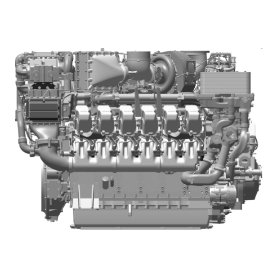
2.2 Engine – Overview The illustration may deviate from the actual engine. 1 Engine oil heat exchanger 11 Charge-air cooler 21 HP fuel pump 2 Wiring harness mount (high pressure) 22 Lube oil filter 3 Exhaust outlet 12 EGR line 23 Engine mounting 4 Air intake 13 Starter... -
Page 22: Back Pack - Overview
2.3 Back Pack – Overview Back Pack – Overview 1 Exhaust silencer 4 Air filter 7 Air intake elbow 2 Rain cap 5 Service indicator 8 Exhaust bellows 3 Air filter 6 Combined support for air/ exhaust system 22 | General Information | MS150096/03E 2015-04... -
Page 23: Sensors, Actuators And Injectors - Overview
2.4 Sensors, actuators and injectors – Overview 1 B13 - Crankshaft speed 3 F57 - Charge-air coolant 2 F70 - Water level in fuel level prefilter (external) 4 F33 - Engine coolant level MS150096/03E 2015-04 | General Information | 23... - Page 24 1 M52 - Bypass flap 5 B91.3 - Exhaust gas pres- 9 B13 - Crankshaft speed 2 B44.2 - Turbocharger B sure 10 B10.11 - Charge-air pres- speed 6 B88 - NOx sure, B-side 3 B90 - Intake air humidity 7 B16 - Engine coolant pres- (pressure, temperature) sure...
- Page 25 1 M55 - Donor cylinder flap 6 B9 - Charge-air tempera- 11 F46 - Leak fuel level 2 B44.3 - Turbocharger C ture 12 B5.3 - Lube oil pressure speed 7 Y39.A1-A6 - Injectors A1- before filter 3 B10.1 - Charge-air pres- 13 B7 - Lube oil temperature sure, A-side 8 B34.3 - Fuel pressure be-...
- Page 26 1 B50 - Crankcase pressure 5 B48 - Fuel pressure (rail) 9 B26 - Charge-air coolant 2 Y44 - Ventilation control 6 M8 - HP fuel pump temperature 3 B5.1 - Lube oil pressure af- 7 B1 - Camshaft speed 10 B6 - Engine coolant tem- ter filter 8 B43 - Charge-air coolant...
-
Page 27: Technical Data
3 Technical Data 3.1 12 V 4000 T94/T94L engine data Explanation Abbrev. Meaning Reference value: Continuous power Reference value: Fuel stop power Design value Guaranteed value Guideline value Limit value up to which the engine can be operated without change (e.g. of power setting) Not yet defined value Not applicable Applicable... - Page 28 Model related data (basic design) Description 12 V 4000 12 V 4000 T94L Engine with exhaust turbocharging (ETC) and charge-air cooling (CAC) Uncooled exhaust lines Number of cylinders Cylinder arrangement: V angle grees (°) Bore Stroke Cylinder displacement Liters 4.77 4.77 Total displacement Liters...
- Page 29 Description 12 V 4000 12 V 4000 T94L Thermostat: Starts to open °C Thermostat: Fully open °C Lube oil system Description 12 V 4000 12 V 4000 T94L Lube oil operating temperature before engine, from °C Lube oil operating temperature before engine, to °C Lube oil temperature before engine, warning °C...
- Page 30 Capacities Description 12 V 4000 12 V 4000 T94L Engine coolant, engine side (w/o cooling system) Liters Charge-air coolant, engine side Liters Total engine oil capacity at initial filling (standard oil system) Liters (option: max. operating inclinations) Oil change volume, max. (standard oil system) Liters (option: max.
-
Page 31: Firing Order
3.2 Firing order Firing order Number of cylinders Firing order A1-B5-A5-B3-A3-B6-A6-B2-A2-B4-A4-B1 MS150096/03E 2015-04 | Technical Data | 31... -
Page 32: Engine - Main Dimensions
3.3 Engine – Main dimensions Engine – Main dimensions Item Dimensions Length (A) approx. 2685 mm Width (B) approx. 1631 mm Height (C) approx. 1921 mm 32 | Technical Data | MS150096/03E 2015-04... -
Page 33: Operation
(>3 months) Preconditions ☑Engine is stopped and starting disabled. ☑MTU Preservation and Represervation Specifications (A001070/..) are available. WARNING In case of out-of-service periods of more than one week: Possible corrosion of components carry- ing air or exhaust gas due to weather conditions, e.g. rain or snow. -
Page 34: Putting The Engine Into Operation After Scheduled Out-Of-Service-Period
4.2 Putting the engine into operation after scheduled out-of- service-period Preconditions ☑Engine is stopped and starting disabled. WARNING In case of out-of-service periods of more than one week: Possible corrosion of components carry- ing air or exhaust gas due to weather conditions, e.g. rain or snow. Risk of injury by flying debris when putting the engine into operation! •... -
Page 35: Operational Checks
4.3 Operational checks DANGER Rotating and moving engine parts. Risk of crushing, danger of parts of the body being caught or pulled in! • Only run the engine at low power. Keep away from the engine's danger zone. WARNING High level of engine noise when the engine is running. Risk of damage to hearing! •... -
Page 36: Starting The Engine In Manual Mode
4.4 Starting the engine in manual mode Preconditions ☑Engine is not under load. ☑External start interlock is not activated. DANGER Rotating, moving engine parts. Risk of crushing! Risk of body parts being caught or drawn in! • Before barring with the starting system, make sure that no one is in the danger zone of the en- gine. -
Page 37: Stopping The Engine In Manual Mode
4.5 Stopping the engine in manual mode Preconditions ☑Engine is not under load. ☑Engine is running in manual mode. NOTICE Stopping the engine in full load operation causes extreme thermal and mechanical stress to the engine. Danger of component damage due to overheating! •... -
Page 38: After Stopping The Engine - Putting The Engine Out Of Operation
4.6 After stopping the engine – Putting the engine out of operation Preconditions ☑MTU Preservation and Represervation Specifications (A001070/..) are available. NOTICE Coolant sensors may freeze if there is a risk of frost. Risk of sensor damage! • Protect sensors from frost. -
Page 39: Plant - Cleaning
4.7 Plant – Cleaning Preconditions ☑Engine is stopped and starting disabled. ☑No operating voltage is applied. Special tools, Material, Spare parts Designation / Use Part No. Qty. Steam jet cleaner Cleaner (Hakupur 50/136) X00056700 WARNING Compressed air gun ejects a jet of pressurized air. Risk of injury to eyes and damage to hearing, risk of rupturing internal organs! •... -
Page 40: Maintenance
5 Maintenance 5.1 Maintenance task reference table [QL1] The maintenance tasks and intervals for this product are defined in the Maintenance Schedule. The Maintenance Schedule is a stand-alone publication. The task numbers in this table provide reference to the maintenance tasks specified in the Maintenance Schedule. - Page 41 Task Maintenance tasks W1577 Check turbine housing externally for cracks, perform endo- (→ Page 100) scopic examination to check it internally for cracks, replace if necessary. W1610 Check securing screws of trunnion bearing for secure seat- (→ Page 159) ing. W1636 Reset parameters of drift correction (CDC) and enter coding (→...
-
Page 42: Troubleshooting
6 Troubleshooting 6.1 Troubleshooting Engine does not turn when starter is actuated Cause Corrective action u Charge or replace (→ manufacturer's documentation). Battery/UltraCaps low or faulty u Check cable connections for secure seating (→ manufacturer's Cable connections faulty documentation). Starter: Engine cabling, POM or u Check if cable connections are properly secured , contact starter defective. - Page 43 Engine governor defective u Contact Service Charge-air temperature too high Cause Corrective action Incorrect coolant concentration u Check (→ MTU test kit) Intercooler dirty u Contact Service Engine room: Air-intake u Check fans and air supply/exhaust ducts. temperature too high...
- Page 44 Blue exhaust gas Cause Corrective action Too much engine oil in the u Drain engine oil (→ Page 131) engine Oil separator of crankcase u Replace filter (→ Page 81) breather contaminated u Contact Service Exhaust turbocharger, cylinder head, piston rings or cylinder liner defective White exhaust gas Cause...
-
Page 45: Engine Governor Ecu9 - Fault Messages
6.2 Engine governor ECU9 – Fault messages Possible engine reactions to yellow alarm: Warning, power limitation / reduction, speed limitation, engine stop Possible engine reactions to red alarm: Engine stop, power limitation / reduction, speed limitation, warning 3 – HI T-Fuel Cause Corrective action The fuel temperature at sensor... - Page 46 10 – SS T-Coolant Charge-Air Cooler Cause Corrective action The coolant temperature in the 1. Reduce power. charge-air cooler at sensor B26 2. Check whether alarm 23 is pending. has exceeded limit value 2. 3. Check cooler (plant side) for contamination. Coolant temperature in charge- 4.
- Page 47 27 – HI Level Leak-Off Fuel Cause Corrective action Switch F46 in the collection tank u Contact Service. has tripped. A leak has occurred in the HP fuel system. 30 – SS Engine Overspeed Cause Corrective action u If an emergency stop has been tripped by the engine overspeed Engine speed has exceeded the limit value or the engine test, restart the engine.
- Page 48 36 – HI ETC2 Overspeed Cause Corrective action The speed of the LP 1. Reduce power. turbocharger, B-side, at sensor 2. Contact Service. B44.2 has exceeded limit value 1. The turbocharger speed is too high. Cause: Defect or malfunction of another turbocharger.
- Page 49 63 – HI P-Crankcase Cause Corrective action The crankcase pressure at 1. Reduce power. sensor B50.has exceeded limit 2. Check air filter (plant side) for contamination. value 1. Crankcase pressure is 3. Replace oil mist fine separator (→ Page 81). too high.
- Page 50 83 – LO P-Fuel (Common Rail) Cause Corrective action The HP fuel pressure at sensor u Contact Service. B48 has undershot the limit value. Fuel pressure is too low. 89 – SS Engine Speed Too Low Cause Corrective action The engine speed has undershot 1.
- Page 51 3. Check battery-charging generator (→ Page 156). 4. Contact Service. 186 – AL CAN1 Bus Off Cause Corrective action CAN bus 1 to MTU automation 1. Check plug connections to engine governor (→ Page 165). (e.g. ECU/MAU/SAM) 2. Contact Service. interrupted or faulty.
- Page 52 188 – AL CAN2 Bus Off Cause Corrective action CAN bus 2 to plant-side 1. Check connection between plant-side automation and MTU automation (e.g. Murphy automation. Display) interrupted or faulty. 2. Contact Service. 189 – AL CAN2 Error Passive Cause...
- Page 53 208 – SD P-Charge Air Cause Corrective action The charge-air pressure sensor 1. Check engine wiring (→ Page 160). (B10.1) after charge-air cooler, 2. Contact Service. A-side, supplies incorrect signal or no signal. 211 – SD P-Lube Oil Cause Corrective action The lube oil pressure sensor 1.
- Page 54 220 – SD Level Coolant Water Cause Corrective action The coolant level sensor (F33) 1. Check engine wiring (→ Page 160). supplies incorrect signal or no 2. Contact Service. signal. 221 – SD P-Diff Lube Oil Cause Corrective action Lube oil pressure sensors B5.3 1.
- Page 55 231 – SD Camshaft Speed Cause Corrective action The crankshaft speed sensor 1. Check engine wiring (→ Page 160). (B1) supplies incorrect signal or 2. Contact Service. no signal. 232 – SD Charger 1 Speed Cause Corrective action The speed sensor (B44.1), ETC 1.
- Page 56 322 – AL Wiring Cylinder A2 Cause Corrective action Short circuit fault in injector 1. Check wiring of affected injector (→ Page 160). wiring cylinder A2, or injector 2. Replace injector (→ Page 89). faulty. 3. Contact Service. 323 – AL Wiring Cylinder A3 Cause Corrective action Short circuit fault in injector...
- Page 57 333 – AL Wiring Cylinder B3 Cause Corrective action Short circuit fault in injector 1. Check wiring of affected injector (→ Page 160). wiring cylinder B3, or injector 2. Replace injector (→ Page 89). faulty. 3. Contact Service. 334 – AL Wiring Cylinder B4 Cause Corrective action Short circuit fault in injector...
- Page 58 345 – AL Open Load Cylinder A5 Cause Corrective action Disruption fault in injector wiring 1. Check wiring of affected injector (→ Page 160). cylinder A5. 2. Contact Service. 346 – AL Open Load Cylinder A6 Cause Corrective action Disruption fault in injector wiring 1.
- Page 59 365 – AL Stop SV Ground Wiring Cause Corrective action Short circuit of injector positive 1. Check wiring (→ Page 160). connection to ground of one or 2. Restart engine. more injectors. 3. Contact Service. Short circuit of negative injector connection or of one or more injectors to ground.
- Page 60 454 – SS Power Limitation Active Cause Corrective action Power reduction activated. A 1. Observe additional messages. master alarm than is pending 2. Contact Service. activates derating. 480 – AL Ext. Engine Protection Cause Corrective action The external engine protection 1.
- Page 61 582 – AL Emergency Stop Failed Cause Corrective action The alarm is issued if the engine u Contact Service. fails to come to a standstill during a programmable time after the emergency stop signal is received. 609 – AL Wiring PWM_CM7 Cause Corrective action Cable break or short circuit at...
- Page 62 627 – AL Wiring PWM_CM9 Cause Corrective action Disruption or short circuit in 1. Check engine wiring (→ Page 160). wiring to servomotor of donor 2. Contact Service. flap M55. 628 – AL Wiring PWM_CM10 Cause Corrective action Disruption or short circuit in 1.
- Page 63 647 – SD P-Exhaust Lambda Cause Corrective action The exhaust pressure sensor 1. Check engine wiring (→ Page 160). (B91.3) supplies incorrect signal 2. Contact Service. or no signal. 648 – SD P-Charge Air B Cause Corrective action The charge-air pressure sensor 1.
- Page 64 764 – AL EASF B to A Open Cause Corrective action After tripping (test / overspeed) 1. Check wiring for emergency-air shutoff flap, A-side of emergency-air shutoff flaps, (→ Page 160). B-side remains closed and A- 2. Contact Service. side remains open. 765 –...
- Page 65 834 – AL Gas Line Warning Cause Corrective action Emission fault summary alarm 1. Observe additional messages. 2. Contact Service. 835 – AL Gas Line Fault Cause Corrective action Emission fault summary alarm 1. Observe additional messages. 2. Contact Service. 839 –...
- Page 66 877 – AL Flap Bypass A Ref learn failed Cause Corrective action Fast reference run of EGR 1. Check charge state of the batteries (plant side). shutoff flap (M52) (executed 2. Check operation of bypass flap (→ Page 122). after each ECU restart) faulty. 3.
- Page 67 958 – AL Lambda ctrlvar limit min active Cause Corrective action The charge-air controller 1. Check operation of donor flap (→ Page 122). attempts to set a set value but 2. Contact Service. has reached the lower limit. The EGR shutoff flap (M53) is fully closed.The donor flap (M55) is fully open.
- Page 68 962 – AL GPS Lambda ctrlvar max active Cause Corrective action The fault indicates high 1. Check operation of EGR shutoff flap, donor flap and bypass flap probability of serious soot (→ Page 122). deposits in the EGR cooler 2. Contact Service. (sooting).
- Page 69 975 – AL CAN3 Error Passive Cause Corrective action The first Engine-CAN (CAN 3) to 1. Check engine wiring (→ Page 160). the engine-side sensor / 2. Contact Service. actuator system is interrupted or defective. 976 – AL CAN4 Bus Off Cause Corrective action The second Engine-CAN (CAN 4)
- Page 70 1103 – AL Flap Bypass A Communication Lost Cause Corrective action The ECU can no longer detect 1. Check engine wiring (→ Page 160). the bypass flap (M52) on the 2. Contact Service. bus. 1104 – AL Flap Bypass A Temperature too high Cause Corrective action u Contact Service.
- Page 71 1116 – AL Difference P0 P1 Intake Air L2 Cause Corrective action The differential pressure at 1. Check air filter (plant side) for contamination. sensor B90 and the ambient air 2. Contact Service. pressure sensor integrated in the ECU has exceeded limit value 2.
- Page 72 1172 – AL Implausible NOx High Limit2 Cause Corrective action NOx emissions too high. The u Contact Service. cumulative NOx emissions from the engine have exceeded limit value 2. 1186 – AL EGR FlpA Wear Limit2 Cause Corrective action Fast reference run of EGR 1.
-
Page 73: Task Description
7 Task Description 7.1 Engine 7.1.1 Engine – Barring manually Preconditions ☑Engine is stopped and starting disabled. Special tools, Material, Spare parts Designation / Use Part No. Qty. Barring gear F6792918 Barring gear F6555766 Ratchet with extension F30006212 DANGER Rotating and moving engine parts. Risk of crushing, danger of parts of the body being caught or pulled in! •... - Page 74 Note: Use barring gear F6555766. Engage barring gear (2) in ring gear of fly- wheel and mount on flywheel housing. Fit ratchet (1) on barring gear. Note: No resistance other than compression re- sistance may be encountered. Rotate crankshaft in engine direction of ro- tation.
-
Page 75: Barring Engine With Starting System
7.1.2 Barring engine with starting system DANGER Rotating and moving engine parts. Risk of crushing, danger of parts of the body being caught or pulled in! • Before barring the engine, make sure that there are no persons in the engine's danger zone. •... -
Page 76: Engine - Test Run
7.1.3 Engine – Test run DANGER Rotating and moving engine parts. Risk of crushing, danger of parts of the body being caught or pulled in! • Before cranking the engine with starter system, make sure that there are no persons in the en- gine's danger zone. -
Page 77: Cylinder Liner
7.2 Cylinder Liner 7.2.1 Cylinder liner – Endoscopic examination Preconditions ☑Engine is stopped and starting disabled Special tools, Material, Spare parts Designation / Use Part No. Qty. Barring device F6555766 Ratchet with extension F30006212 Endoscope Y20097353 Preparatory steps Remove cylinder head cover (→ Page 86). Remove injector (→... - Page 78 Compile endoscopic report using the table. Use technical terms to describe the liner surface (→ Page 79). Depending on findings: • Do not take any action or • carry out a further endoscopic examination as part of maintenance work or •...
-
Page 79: Instructions And Comments On Endoscopic And Visual Examination Of Cylinder Liners
7.2.2 Instructions and comments on endoscopic and visual examination of cylinder liners Terms used for endoscopic examination Use the terms listed below to describe the condition of the cylinder-liner surface in the endoscopic ex- amination report. Findings Explanations/Action Minor dirt scores Minor dirt scores can occur during the assembly of a new engine (honing products, particles, broken-off burrs). - Page 80 Evaluation of findings and further measures The findings in the start phase of oxidation discoloration and heat discoloration are similar. A thorough investigation and compliance with the above evaluation criteria allow an unambiguous evaluation. To avoid unnecessary disassembly work, it is recommended that another inspection be carried out after further operation of the engine.
-
Page 81: Crankcase Breather
7.3 Crankcase Breather 7.3.1 Oil mist fine separator – Replacement Preconditions ☑Engine is stopped and starting disabled. Special tools, Material, Spare parts Designation / Use Part No. Qty. Engine oil Oil mist fine separator (→ Spare Parts Catalog) O-ring (→ Spare Parts Catalog) WARNING Hot oil. -
Page 82: Valve Drive
7.4 Valve Drive 7.4.1 Valve gear – Lubrication Preconditions ☑Engine is stopped and starting disabled. Special tools, Material, Spare parts Designation / Use Part No. Qty. Engine oil Valve gear – Lubrication Remove cylinder head covers (→ Page 86). Fill oil chambers of valve bridges with oil. Fill oil chambers of rocker arms and adjust- ing screws with oil. -
Page 83: Valve Clearance - Check And Adjustment
7.4.2 Valve clearance – Check and adjustment Preconditions ☑Engine is stopped and starting disabled. ☑Coolant temperature max. 40 °C. ☑Valves are closed. Special tools, Material, Spare parts Designation / Use Part No. Qty. Feeler gauge Y20098771 Allen key F30002815 Torque wrench, 60-320 Nm F30452768 Socket wrench, 24 mm F30039526... -
Page 84: Adjusting Valve Clearance
Diagram for 12V engines (two crankshaft positions) 1 Cylinder A1 is in firing TDC 2 Cylinder A1 is in overlap TDC I Inlet valve X Exhaust valve Checking valve clearance at two crankshaft positions Check OT/TDC position of piston in cylinder A1: •... - Page 85 Final steps Remove barring device (→ Page 73). Install cylinder head cover (→ Page 86). Enable engine start. MS150096/03E 2015-04 | Task Description | 85...
-
Page 86: Cylinder Head Cover - Removal And Installation
7.4.3 Cylinder head cover ‒ Removal and installation Preconditions ☑Engine is stopped and starting disabled. Special tools, Material, Spare parts Designation / Use Part No. Qty. Assembly compound (Kluthe Hakuform 30-15) X00067260 O-ring (→ Spare Parts Catalog) Removing cylinder head cover Clean cylinder head covers (1) if severely soiled prior to removal. -
Page 87: Injection Pump / Hp Pump
7.5 Injection Pump / HP Pump 7.5.1 HP pump – Filling with engine oil Preconditions ☑Engine is stopped and starting disabled. Special tools, Material, Spare parts Designation / Use Part No. Qty. Engine oil WARNING Fuels are combustible. Risk of fire and explosion! •... - Page 88 Filling HP pump Remove plug screw (1). Use pump oiler to fill HP pump with engine oil until engine oil emerges. Screw in plug screw (1). 88 | Task Description | MS150096/03E 2015-04...
-
Page 89: Injection Valve / Injector
7.6 Injection Valve / Injector 7.6.1 Injector – Replacement Special tools, Material, Spare parts Designation / Use Part No. Qty. Injector (→ Spare Parts Catalog) Injector – Replacement Remove injector and install new one (→ Page 90). MS150096/03E 2015-04 | Task Description | 89... -
Page 90: Injector - Removal And Installation
7.6.2 Injector – Removal and installation Preconditions ☑Engine is stopped and starting disabled. Special tools, Material, Spare parts Designation / Use Part No. Qty. Puller F6790506 Press-in tool F6796354 Milling cutter F30452739 Torque wrench, 1-5 Nm F30452774 Torque wrench, 10-60 Nm F30452769 Torque wrench, 60–320 Nm F30452768... - Page 91 Unscrew union nuts (2, 5) and remove HP line (3) from rail (4) and cylinder head. Note: While the adapter is removed, the injector is drained. Provide suitable container to collect escap- ing fuel. Remove adapter (1). Remove screw (2) from hold-down clamp (1).
-
Page 92: Installing Injector
Installing injector Note: Remove plugs on HP line only before instal- lation of the adapter. Prior to installation, remove all plugs. Coat injector with assembly paste at the seat of the nozzle retaining nut. Note: New sealing ring is included in the injector scope of delivery. - Page 93 Coat screw head mating face and thread (2) of hold-down clamp (1) with en- gine oil. Insert screw (2) and tighten with torque wrench to the specified initial tightening torque. Name Size Type Lubricant Value/Standard Screw Preload torque (Engine oil) 5 Nm to 10 Nm Note: Ensure special cleanness.
- Page 94 Use torque wrench to tighten union nuts (2, 5) on HP line (3) to specified tightening torque. Tightening sequence: 1 Counterhold nuts on adapter (2) and adapter (1). 2 Nut on rail (5) Name Size Type Lubricant Value/Standard Union nut / thrust Tightening torque (Engine oil) 40 Nm +5 Nm...
-
Page 95: Fuel System
7.7 Fuel System 7.7.1 Fuel system – Venting Preconditions ☑Engine is stopped and starting disabled. Special tools, Material, Spare parts Designation / Use Part No. Qty. Diesel fuel WARNING Fuels are combustible and explosive. Risk of fire and explosion! • Avoid open flames, electrical sparks and ignition sources. •... -
Page 96: Fuel Filter
7.8 Fuel Filter 7.8.1 Fuel filter – Replacement Preconditions ☑Engine is stopped and starting disabled. Special tools, Material, Spare parts Designation / Use Part No. Qty. Filter wrench F30379104 Engine oil Easy-change filter (→ Spare Parts Catalog) WARNING Fuels are combustible and explosive. Risk of fire and explosion! •... -
Page 97: Additional Fuel Filter - Replacement
7.8.2 Additional fuel filter – Replacement Preconditions ☑Engine is stopped and starting disabled. Special tools, Material, Spare parts Designation / Use Part No. Qty. Filter wrench F30379104 Engine oil Easy-change filter (→ Spare Parts Catalog) WARNING Fuels are combustible. Risk of fire and explosion! •... -
Page 98: Fuel Prefilter - Draining
7.8.3 Fuel prefilter – Draining Preconditions ☑Engine is stopped and starting disabled. Special tools, Material, Spare parts Designation / Use Part No. Qty. Diesel fuel WARNING Fuels are combustible. Risk of fire and explosion! • Avoid open flames, electrical sparks and ignition sources. •... -
Page 99: Fuel Prefilter - Filter Element Replacement
7.8.4 Fuel prefilter – Filter element replacement Preconditions ☑Engine is stopped and starting disabled. Special tools, Material, Spare parts Designation / Use Part No. Qty. Diesel fuel Filter element (→ Spare Parts Catalog) Gasket (→ Spare Parts Catalog) WARNING Fuels are combustible. Risk of fire and explosion! •... -
Page 100: Exhaust Turbocharger
7.9 Exhaust Turbocharger 7.9.1 Exhaust turbocharger – Turbine housing check Special tools, Material, Spare parts Designation / Use Part No. Qty. Turbine housing (→ Spare Parts Catalog) Exhaust turbocharger (low-pressure charger) Check turbine housing (→ Page 101). Exhaust turbocharger (high pressure) Check turbine housing (→... -
Page 101: Exhaust Turbocharger (Lp) - Turbine Housing Check
7.9.2 Exhaust turbocharger (LP) – Turbine housing check Preconditions ☑Engine is stopped and starting disabled. ☑MTU Fluids and Lubricants Specifications (A001061/..) are available. Special tools, Material, Spare parts Designation / Use Part No. Qty. Endoscope Y20097353 Torque wrench, 10-60 Nm F30452769 Torque wrench, 60–320 Nm... - Page 102 Remove NOx sensor (1) from exhaust el- bow. Preparatory steps – exhaust tur- bocharger (LP), left side Release screws on holders (2, 3). Remove holders (2, 3) with coolant vent lines (1, 4) from heat shield. Remove temperature sensor (1), lambda sensor (2) and measurement line for sen- sor B91.3 (3) from exhaust elbow.
- Page 103 Note: The following work steps are described for one exhaust turbocharger (LP) only. The description also ap- plies mirror-inverted for the other side. Check the turbine housing of the exhaust turbocharger (HP) re- quires special work steps (→ Page 109). Removing heat shield Remove screws (1) and take off with hold- er (2) and washers.
- Page 104 Removing exhaust elbow Note: Mark position of clamp. Unscrew screws (4) and remove with spacer sleeves (5) from mounting bracket. Release clamp (2) and take off with sealing ring (3) and exhaust elbow (1) from turbine housing. Checking turbine housing Note: Cracks are only permissible in the direction of circumference of the spiral.
- Page 105 Tightening torque (Assembly paste (Ul- 27 Nm +2 Nm tra-Therm MTU)) Coat screw threads of screws (4) with assembly paste prior to installation. Install screws (4) and spacer sleeve (5) on mounting bracket and tighten to specified tightening torque. Name...
- Page 106 Final steps – exhaust turbo- charger (LP), right side Install NOx sensor (1) on exhaust elbow and use torque wrench and socket for NOx sensor to tighten to specified tightening torque. Name Size Type Lubricant Value/Standard Sensor M20 x 1.5 Tightening torque 50 Nm ±10 Nm Install pipe clamp halves (2, 3) and coolant vent lines (1, 4) on heat shield and holder.
- Page 107 Final steps – exhaust turbo- charger (LP), left side Install lambda sensor (1) on exhaust elbow and use torque wrench and socket for lambda sensor to tighten to specified tightening torque. Name Size Type Lubricant Value/Standard Sensor M18 x 1.5 Tightening torque 50 Nm ±10 Nm Install measurement to pressure sensor B91.3 (2) on exhaust elbow and tighten union with union nut.
- Page 108 Install coolant vent lines (1, 4) and hold- ers (2, 8) on heat shield and tighten screws. Final steps, general Fill with engine coolant (→ Page 142). Fill charge-air coolant (→ Page 151). 108 | Task Description | MS150096/03E 2015-04...
-
Page 109: Exhaust Turbocharger (Hp) - Turbine Housing Check
7.9.3 Exhaust turbocharger (HP) – Turbine housing check Preconditions ☑Engine is stopped and starting disabled. ☑MTU Fluids and Lubricants Specifications (A001061/..) are available. Special tools, Material, Spare parts Designation / Use Part No. Qty. Torque wrench, 10-60 Nm F30452769 Torque wrench, 60–320 Nm... - Page 110 Note: The procedure is only described for the exhaust turbocharger (HP). Checking of the exhaust turbocharg- er turbine housing (LP) requires separate activities (→ Page 101). Removing heat shield Remove screws (1) and take off with hold- er (2) and washers. Remove screws (2) and take off with heat shield (1) and washers.
- Page 111 Removing exhaust pipe Release clamp (2) and take off with ex- haust pipe (3) and sealing ring (1) from tur- bine housing. Removing insulation of exhaust pipe bellows Release clamps (1) and remove insulation (2). Checking turbine housing Note: Cracks are only permissible in the direction of circumference of the spiral.
- Page 112 Tighten nut of clamp (2) with torque wrench to specified tightening torque. Name Size Type Lubricant Value/Standard Tightening torque (Assembly paste (Ul- 27 Nm +2 Nm tra-Therm MTU)) Installing exhaust pipe insula- tion Install insulation (2) on exhaust pipe and secure with clamps (1). 112 | Task Description | MS150096/03E 2015-04...
- Page 113 Installing heat shield Install heat shield (1) with washers and screws (2) and tighten to specified tightening torque. Name Size Type Lubricant Value/Standard Screws Tightening torque (Engine oil) 42 Nm +4 Nm Install holder (2) with washers and screws (1) and washers and tighten. MS150096/03E 2015-04 | Task Description | 113...
- Page 114 Final steps Install coolant vent lines (2, 4) and hold- ers (1, 3) on heat shield and tighten screws. Fill with engine coolant (→ Page 142). File charge-air coolant (→ Page 151). 114 | Task Description | MS150096/03E 2015-04...
-
Page 115: Charge-Air Cooling
7.10 Charge-Air Cooling 7.10.1 Intercooler – Leak check DANGER Rotating, moving engine parts. Risk of crushing! Risk of body parts being caught or drawn in! • Take special care when the engine is running. • Stay well clear of danger zones at the engine. WARNING Loud engine noises with the engine running: Risk of hearing damage! -
Page 116: Air Filter
7.11 Air Filter 7.11.1 Air filter – Replacement Preconditions ☑Engine is stopped and starting disabled. Air filter – Replacement Release latches (1). Remove cover (2). Remove filter insert (3) and filter ele- ment (4). Wipe out filter housing (5) and cover (2) with a damp cloth. -
Page 117: Air Intake
7.12 Air Intake 7.12.1 Service indicator – Signal ring position check Preconditions ☑Engine is stopped and starting disabled. Checking signal ring position If the signal ring is completely visible in the control window (2), replace air filter (→ Page 116). After installation of new filter, press reset button (1). -
Page 118: Emergency-Air Shutoff Flaps - Functional Check With Electric Actuation
7.12.2 Emergency-air shutoff flaps – Functional check with electric actuation DANGER Rotating and moving engine parts. Risk of crushing, danger of parts of the body being caught or pulled in! • Before cranking the engine with starter system, make sure that there are no persons in the en- gine's danger zone. - Page 119 Option 2: Check function while engine is running Check both emergency-air shutoff flaps and their wiring for mechanical damage. Make sure that the pointers (1) of both emergency-air shutoff flaps are pointing to OPEN / ON and the emergency-air shutoff flaps are open.
-
Page 120: Exhaust Gas Recirculation
7.13 Exhaust Gas Recirculation 7.13.1 Exhaust flaps – Overview 1 EGR shutoff flap 2 Donor cylinder flap 120 | Task Description | MS150096/03E 2015-04... - Page 121 1 Bypass flap MS150096/03E 2015-04 | Task Description | 121...
-
Page 122: Exhaust Flaps - Checking Operation Of Actuators
7.13.2 Exhaust flaps – Checking operation of actuators Preconditions ☑Engine is stopped and starting disabled. ☑Operating voltage is not applied. WARNING Actuation mechanism in the exhaust and intake area closes automatically. Risk of crushing hands! • To carry out the teach-in routine, keep clear of the safety zone of the actuation mechanism in the intake and exhaust area. -
Page 123: Exhaust Flaps - Checking Coupling Rods Operability And Play
7.13.3 Exhaust flaps – Checking coupling rods operability and play Preconditions ☑Engine is stopped and starting disabled. ☑No operating voltage is applied. WARNING Actuation mechanism in the exhaust and intake area closes automatically. Risk of crushing hands! • To carry out the teach-in routine, keep clear of the safety zone of the actuation mechanism in the intake and exhaust area. - Page 124 Check operability and ease of movement of coupling rod (1) by moving it at the speci- fied points (arrowed) and make sure that there is no excessive play. Result: Replace coupling rod (1) if it is jamming, sluggish or features excessive play (→...
-
Page 125: Exhaust Flaps - Coupling Rod Replacement
Special tools, Material, Spare parts Designation / Use Part No. Qty. Torque wrench, 6-50 Nm F30027336 Ratchet adapter F30027340 Assembly paste (Ultra-Therm MTU) 50547 Coupling rod (→ Spare Parts Catalog) Coupling rod (→ Spare Parts Catalog) Locknut (→ Spare Parts Catalog) Locking screw (→... - Page 126 Size Type Lubricant Value/Standard Nut / screw Tightening torque (Assembly paste (Ul- 6 Nm + 2 Nm tra-Therm MTU)) Tighten washers (1) and locknuts (2) to the specified tightening torque. Name Size Type Lubricant Value/Standard Tightening torque (Assembly paste (Ul- 16 Nm ±...
- Page 127 Size Type Lubricant Value/Standard Nut / screw Tightening torque (Assembly paste (Ul- 6 Nm + 2 Nm tra-Therm MTU)) Tighten washers (3) and locknuts (4) to the specified tightening torque. Name Size Type Lubricant Value/Standard Tightening torque (Assembly paste (Ul- 16 Nm ±...
-
Page 128: Starter – Condition Check
7.14 Starting Equipment 7.14.1 Starter – Condition check Preconditions ☑Engine is stopped and starting disabled. Checking starter condition Check securing screws of starter for secure seating and tighten if required. Check wiring (→ Page 160). 128 | Task Description | MS150096/03E 2015-04... -
Page 129: Engine Oil Level – Check At Sight Glass
7.15 Lube Oil System, Lube Oil Circuit 7.15.1 Engine oil level – Check at sight glass Preconditions ☑Engine is stopped and starting disabled. Engine oil level check at sight glass Make a preliminary visual check of oil lev- el (2) at the sight glass (1). A proper engine oil level check must al- ways be carried out using the oil dipstick (→... -
Page 130: Engine Oil – Level Check With Oil Dipstick
7.15.2 Engine oil – Level check with oil dipstick Checking oil level prior to en- gine start Pull out dipstick from guide tube and wipe Insert dipstick into guide tube up to the stop, pull out after approx. 10 seconds. Check oil level on oil dipstick side marked "5 Min. -
Page 131: Engine Oil – Change
7.15.3 Engine oil – Change Preconditions ☑Engine is stopped and starting disabled. ☑Engine is at operating temperature. ☑MTU Fluids and Lubricants Specifications (A001061/..) are available. Special tools, Material, Spare parts Designation / Use Part No. Qty. Torque wrench, 40-200 Nm... - Page 132 Draining residual oil from equip- ment carrier (only with un- scheduled engine oil change) Provide a suitable container in which to col- lect the engine oil. Remove drain plug (1) and drain engine oil from engine oil heat exchanger and from engine oil filter.
-
Page 133: Engine Oil – Sample Extraction And Analysis
7.15.4 Engine oil – Sample extraction and analysis Preconditions ☑MTU Fluids and Lubricants Specifications (A001061/..) are available. Special tools, Material, Spare parts Designation / Use Part No. Qty. MTU test kit 5605892099/00 DANGER Rotating and moving engine parts. Risk of crushing, danger of parts of the body being caught or pulled in! •... -
Page 134: Engine Oil Filter – Replacement
7.16 Oil Filtration / Cooling 7.16.1 Engine oil filter – Replacement Preconditions ☑Run engine to reach operating temperature. Special tools, Material, Spare parts Designation / Use Part No. Qty. Filter wrench F30379104 Engine oil Oil filter (→ Spare Parts Catalog) Sealing ring (→... - Page 135 Remove engine oil filter using the filter wrench. Clean sealing surface on connecting piece. Note: Only install engine oil filter with an integrat- ed safety valve. Check condition of the new oil filter sealing ring and coat it with engine oil. Screw the engine oil filter on and tighten by hand.
-
Page 136: Centrifugal Oil Filter – Cleaning And Filter Sleeve Replacement
7.16.2 Centrifugal oil filter – Cleaning and filter sleeve replacement Preconditions ☑Engine is stopped and starting disabled. Special tools, Material, Spare parts Designation / Use Part No. Qty. Filter wrench F30379104 Torque wrench, 6-50 Nm F30027336 Ratchet adapter F30027339 Solvent cleaner (Hakutex 60) X00056750 Assembly compound (Kluthe Hakuform 30-11C/Emulgier) X00059351... - Page 137 Centrifugal oil filter – Cleaning and filter sleeve replacement Loosen screw (1) and remove. Remove clamp (3) and take off hood (2). Carefully remove rotor (5) from housing. Hold rotor assembly (5) firmly in position with filter wrench and loosen knurled nut (7).
-
Page 138: Engine Coolant – Level Check
7.17 High-Temperature Circuit 7.17.1 Engine coolant – Level check Preconditions ☑Engine is stopped and starting disabled. ☑MTU Fluids and Lubricants Specifications (A001061/..) are available. WARNING Coolant is hot and under pressure. Risk of injury and scalding! • Let the engine cool down. -
Page 139: Engine Coolant – Change
7.17.2 Engine coolant – Change Special tools, Material, Spare parts Designation / Use Part No. Qty. Coolant Engine coolant change Drain engine coolant (→ Page 140). Fill with engine coolant (→ Page 142). MS150096/03E 2015-04 | Task Description | 139... -
Page 140: Engine Coolant – Draining
7.17.3 Engine coolant – Draining Preconditions ☑Engine is stopped and starting disabled. WARNING Coolant is hot and highly pressurized. Risk of injury! Risk of scalding! • Allow engine to cool down. • Wear protective clothing, protective gloves, and safety glasses / facial protection. Preparatory steps Provide a suitable container to collect the coolant. - Page 141 Drain remaining engine coolant at EGR cooler, A and B side (arrow). Final steps Close all open drain points. Fit cover on filler neck and close it. MS150096/03E 2015-04 | Task Description | 141...
-
Page 142: Engine Coolant – Filling
7.17.4 Engine coolant – Filling Preconditions ☑Engine is stopped and starting disabled. ☑MTU Fluids and Lubricants Specifications (A001061/..) are available. Special tools, Material, Spare parts Designation / Use Part No. Qty. Engine coolant WARNING Coolant is hot and highly pressurized. - Page 143 Filling with engine coolant using pump Connect appropriate pump with hose to drain valve (1). Open vent points on EGR cooler (1, 7), dis- tributor pieces (4, 6), exhaust turbocharg- ers (2, 3) and oil heat exchanger (5). Open drain valve and pump coolant into en- gine at 0.5 bar minimum.
- Page 144 Alternatively: Filling with cool- ant through filler neck Open vent points on EGR cooler (1, 7), dis- tributor pieces (4, 6), exhaust turbocharg- ers (2, 3) and oil heat exchanger (5). Fill in coolant in expansion tank via filler neck until coolant level at top edge of filler neck remains constant.
-
Page 145: Engine Coolant Pump – Relief Bore Check
7.17.5 Engine coolant pump – Relief bore check DANGER Rotating, moving engine parts. Risk of crushing! Risk of body parts being caught or drawn in! • Take special care when the engine is running. • Stay well clear of danger zones at the engine. WARNING Loud engine noises with the engine running: Risk of hearing damage! -
Page 146: Charge-Air Coolant – Level Check
7.18 Low-Temperature Circuit 7.18.1 Charge-air coolant – Level check Preconditions ☑Engine is stopped and starting disabled. ☑MTU Fluids and Lubricants Specifications (A001061/..) are available. WARNING Coolant is hot and under pressure. Risk of injury and scalding! • Let the engine cool down. -
Page 147: Charge-Air Coolant – Change
7.18.2 Charge-air coolant – Change Special tools, Material, Spare parts Designation / Use Part No. Qty. Coolant Charge-air coolant – Change Drain charge-air coolant (→ Page 148). Fill with charge-air coolant (→ Page 151). MS150096/03E 2015-04 | Task Description | 147... -
Page 148: Charge-Air Coolant – Draining
7.18.3 Charge-air coolant – Draining Preconditions ☑Engine is stopped and starting disabled. ☑Operating voltage is not applied. ☑MTU Fluids and Lubricants Specifications (A001061/..) are available. Special tools, Material, Spare parts Designation / Use Part No. Qty. Sealing ring (→ Spare Parts Catalog) WARNING Component is hot. - Page 149 Drain remaining charge-air coolant at inter- cooler (high pressure) (arrow). Drain remaining charge-air coolant at inter- cooler (low pressure) A-side (arrows). Drain remaining charge-air coolant at inter- cooler (low pressure) B-side (arrow). MS150096/03E 2015-04 | Task Description | 149...
- Page 150 Note: • The procedure is only described for one exhaust flap, but also applies to the re- maining exhaust flaps. Exhaust flap over- view (→ Page 120). • Collect emerging engine coolant in a suitable container. Loosen the union nut (4) of the lower cool- ant line (3).
-
Page 151: Charge-Air Coolant – Filling
7.18.4 Charge-air coolant – Filling Preconditions ☑Engine is stopped and starting disabled. ☑MTU Fluids and Lubricants Specifications (A001061/..) are available. Special tools, Material, Spare parts Designation / Use Part No. Qty. Charge-air coolant WARNING Coolant is hot and highly pressurized. - Page 152 Filling with engine coolant through filler neck Open vent points at charge-air cooler (high pressure) (5), charge-air cooler (low pres- sure) (1, 4) and distributors (2, 3). Fill charge-air coolant in expansion tank via filler neck until charge-air coolant level at top edge of filler neck remains constant.
- Page 153 Open vent points at charge-air cooler (high pressure) (5), charge-air cooler (low pres- sure) (1, 4) and distributors (2, 3). Open drain valve and pump charge-air cool- ant into engine at 0.5 bar minimum. Fill expansion tank until overflow edge is reached.
-
Page 154: Checking Charge-Air Coolant Pump Pressure Relief Port
7.18.5 Checking charge-air coolant pump pressure relief port DANGER Rotating and moving engine parts. Risk of crushing, danger of parts of the body being caught or pulled in! • Only run the engine at low power. Keep away from the engine's danger zone. WARNING High level of engine noise when the engine is running. -
Page 155: Drive Belt – Condition Check
7.19 Belt Drive 7.19.1 Drive belt – Condition check Preconditions ☑Engine is stopped and starting disabled. ☑Guard is removed. Drive belt – Condition check Item Findings Action Drive belt A Singular cracks None Drive belt B Cracks on entire circumference Replace (→... -
Page 156: Checking Battery-Charging Generator
7.20 Battery-Charging Generator 7.20.1 Checking battery-charging generator Preconditions ☑Engine is stopped and starting disabled. WARNING Air jet from compressed-air gun. Risk of injury to eyes and organs! Risk of hearing damage! • Never direct a compressed-air jet at persons. • Wear goggles/safety mask and ear protectors. Checking battery-charging generator Item Findings... -
Page 157: Battery-Charging Generator Drive – Drive Belt Tension Adjustment
7.20.2 Battery-charging generator drive – Drive belt tension adjustment Preconditions ☑Engine is stopped and starting disabled. Special tools, Material, Spare parts Designation / Use Part No. Qty. Torque wrench, 60–320 Nm F30452768 Ratchet F30027341 Torque wrench, 10-60 Nm F30452769 Ratchet F30027340 WARNING Belt tensioner spring is pretensioned. -
Page 158: Battery-Charging Generator Drive – Drive Belt Replacement
7.20.3 Battery-charging generator drive – Drive belt replacement Preconditions ☑Engine is stopped and starting disabled. Special tools, Material, Spare parts Designation / Use Part No. Qty. Torque wrench, 60–320 Nm F30452768 Ratchet F30027341 Torque wrench, 10-60 Nm F30452769 Ratchet F30027340 Drive belt (→... - Page 159 7.21 Engine Mounting / Support 7.21.1 Engine mounting – Check Preconditions ☑Engine is stopped and starting disabled. Special tools, Material, Spare parts Designation / Use Part No. Qty. Torque wrench, 80 to 400 Nm F30027338 Ratchet F30027341 Engine oil Checking general condition Item Findings Action...
-
Page 160: Wiring (General) For Engine/Gearbox/Unit
7.22 Wiring (General) for Engine/Gearbox/Unit 7.22.1 Engine cabling – Check Preconditions ☑Engine is stopped and starting disabled. Special tools, Material, Spare parts Designation / Use Part No. Qty. Solvent (isopropyl alcohol) X00058037 Engine cabling – Check Check securing screws of cable clamps on engine and tighten loose screw connections. Ensure that cables are securely seated in clamps and cannot move freely. -
Page 161: Resetting Cdc Parameter And Entering Iig With Diasys
7.23 Accessories for (Electronic) Engine Governor / Control System 7.23.1 Resetting CDC parameter and entering IIG with DiaSys® Preconditions ☑Engine is stopped and starting disabled. Note: If the parameters for the drift correction (CDC) are not reset, the emission certification becomes invalid. Resetting parameters for drift correction (CDC) with DiaSys®... -
Page 162: Actuators – Visual Inspection And Test
7.23.2 Actuators – Visual inspection and test Preconditions ☑Engine is stopped and starting disabled. WARNING Actuation mechanism in the exhaust and intake area closes automatically. Risk of crushing hands! • To carry out the teach-in routine, keep clear of the safety zone of the actuation mechanism in the intake and exhaust area. - Page 163 Measure Item Findings Connector (1) Damaged Replace Actuator cable connection (2) Damaged, protective cap not seat- Replace, fit protective cap correct- ed correctly. Actuator general condition Heavily contaminated by black ex- Replace haust. Checking actuators with DiaSys® Note: For installation position of exhaust flaps, refer to overview (→ Page 120). Switch on ECU.
- Page 164 7.23.3 Engine governor and connector – Cleaning Preconditions ☑Engine is stopped and starting disabled. Special tools, Material, Spare parts Designation / Use Part No. Qty. Solvent (isopropyl alcohol) X00058037 Note: Always use test connectors to enter the connectors. Never use test leads for this purpose. Otherwise the contacts could be bent.
- Page 165 7.23.4 Engine governor plug connections – Check Preconditions ☑Engine stopped and starting disabled. NOTICE Insertion of unsuitable test probe, e.g. test prod. The contacts in the plug connection can be bent! • Carry out check of plug connection only with test connectors. Checking plug connections at engine governor Check all plug connections for secure seating.
- Page 166 7.23.5 NOx sensor – Replacement Preconditions ☑Engine is stopped and starting disabled. Special tools, Material, Spare parts Designation / Use Part No. Qty. Torque wrench, 20–100 Nm F30026582 Ratchet adapter F30027340 Assembly compound (Molykote P 37) 50564 NOx sensor (→ Spare Parts Catalog) WARNING Hot components/surfaces.
- Page 167 Installing NOx sensor Note: Note the following: • If the sensor (3) was subjected to shock or impact load, it is considered to be defective and may not be used. • Always replace NOx sensor (3) together with control unit (1). Install control unit (1) at the eyelets and tighten screws to the specified tightening torque.
-
Page 168: Lambda Sensor – Replacement
7.23.6 Lambda sensor – Replacement Preconditions ☑Engine is stopped and starting disabled. Special tools, Material, Spare parts Designation / Use Part No. Qty. Torque wrench, 20-100 Nm F30026582 Ratchet adapter F30027340 Assembly compound (Molykote P 37) 50564 Lambda sensor (→ Spare Parts Catalog) WARNING Hot components/surfaces. - Page 169 Installing Lambda sensor Note: When the sensor was subjected to shock or impact load, it is deemed to be defective and may not be used. Remove protective cap on thread only just before installation. Note: Do not wipe off the thread lubricant applied by the manufacturer.
-
Page 170: Exhaust System
7.24 Exhaust System 7.24.1 Exhaust silencer – Condensate drain check Preconditions ☑Engine is stopped and starting disabled. Exhaust silencer – Condensate drain check Provide a suitable container to collect the condensate. Open drain plug (1). Allow the condensate to drain off. Close drain plug (1). -
Page 171: Back Pack – Visual Inspection Of Securing Screws
7.24.2 Back Pack – Visual inspection of securing screws Preconditions ☑Engine is stopped and starting disabled. Back Pack – Visual inspection of securing screws Measure Item Findings Check securing screws for damage and de- Damaged, deformation visi- Replace formation. ble. MS150096/03E 2015-04 | Task Description | 171... -
Page 172: Back Pack – Checking Securing Screws For Firm Seating
7.24.3 Back Pack – Checking securing screws for firm seating Preconditions ☑Engine is stopped and starting disabled. Special tools, Material, Spare parts Designation / Use Part No. Qty. Torque wrench, 10-60 Nm F30452769 Torque wrench, 60-320 Nm F30452768 Check securing screws for firm seating Check-tighten securing screws (1). - Page 173 Check-tighten securing screws (1). Name Size Type Lubricant Value/Standard Screw M10x50 Tightening torque 79 Nm MS150096/03E 2015-04 | Task Description | 173...
- Page 174 Abgasturbolader Exhaust turbocharger (ETC) Air Temperature Sensor Baureihe Series Betriebsstoffvorschrift Fluids and Lubricants Specifications, MTU Publica- tion No. A01061/.. Controller Area Network Data bus system, bus standard Calibration Drift Compensation Drift correction setting with DiaSys in engine gover- Check Engine Light...
- Page 175 Abbre- Meaning Explanation viation Engine Data Module Memory module for engine data Electrically Erasable Programmable Read PROM Only Memory EFPA Electronic Foot Pedal Assembly Electronic accelerator pedal Exhaust Gas Recirculation Engine Ident Label EIM-ID Emission Identification Number Engine Monitoring Unit ESCM Extreme Site Condition Management Power reduction with extreme site conditions...
- Page 176 Abbre- Meaning Explanation viation Not Applicable Normalnull Reference area for heights above sea level Original Equipment Manufacturer Optimized Idle Oil Level Sensor Monitors oil level Oil Pressure Sensor Monitors oil pressure Oil Temperature Sensor Monitors oil temperature Oberer Totpunkt Top Dead Center (TDC) Panel Control panel Peripheral Interface Module...
- Page 177 Local support Experienced and qualified specialists place their knowledge and expertise at your disposal. For locally available support, go to the MTU Internet site: http://www.mtu-online.com 24h hotline With our 24h hotline and the outstanding flexibility of our service staff, we are always ready to assist you –...
-
Page 178: Special Tools
9 Appendix B 9.1 Special Tools Allen key Part No.: F30002815 Qty.: Used in: 7.4.2 Valve clearance – Check and adjustment (→ Page 83) Barring device Part No.: F6555766 Qty.: Used in: 7.2.1 Cylinder liner – Endoscopic examination (→ Page 77) Barring gear Part No.: F6792918... - Page 179 Barring gear Part No.: F6555766 Qty.: Used in: 7.1.1 Engine – Barring manually (→ Page 73) Endoscope Part No.: Y20097353 Qty.: Used in: 7.2.1 Cylinder liner – Endoscopic examination (→ Page 77) Qty.: Used in: 7.9.2 Exhaust turbocharger (LP) – Turbine housing check (→...
- Page 180 Milling cutter Part No.: F30452739 Qty.: Used in: 7.6.2 Injector – Removal and installation (→ Page 90) MTU test kit Part No.: 5605892099/00 Qty.: Used in: 7.15.4 Engine oil – Sample extraction and analysis (→ Page 133) Plug-in open-end wrench, 17 mm Part No.:...
- Page 181 Plug-in open-end wrench, 27 mm Part No.: F30029816 Qty.: Used in: 7.6.2 Injector – Removal and installation (→ Page 90) Press-in tool Part No.: F6796354 Qty.: Used in: 7.6.2 Injector – Removal and installation (→ Page 90) Puller Part No.: F6790506 Qty.: Used in:...
- Page 182 Ratchet Part No.: F30450902 Qty.: Used in: 7.15.3 Engine oil – Change (→ Page 131) Ratchet Part No.: F30027340 Qty.: Used in: 7.20.2 Battery-charging generator drive – Drive belt tension adjustment (→ Page 157) Qty.: Used in: 7.20.3 Battery-charging generator drive – Drive belt re- placement (→...
- Page 183 Ratchet with extension Part No.: F30006212 Qty.: Used in: 7.1.1 Engine – Barring manually (→ Page 73) Qty.: Used in: 7.2.1 Cylinder liner – Endoscopic examination (→ Page 77) Socket for lambda sensor / NOx sensor Part No.: F30453932 Qty.: Used in: 7.9.2 Exhaust turbocharger (LP) –...
- Page 184 Torque wrench, 1-5 Nm Part No.: F30452774 Qty.: Used in: 7.6.2 Injector – Removal and installation (→ Page 90) Torque wrench, 10-60 Nm Part No.: F30452769 Qty.: Used in: 1.4 Crankshaft transport locking device (→ Page 9) Qty.: Used in: 7.6.2 Injector –...
- Page 185 Torque wrench, 20–100 Nm Part No.: F30026582 Qty.: Used in: 7.23.5 NOx sensor – Replacement (→ Page 166) Torque wrench, 300-800 Nm Part No.: F30047798 Qty.: Used in: 7.15.3 Engine oil – Change (→ Page 131) Torque wrench, 40-200 Nm Part No.: F30027337 Qty.:...
- Page 186 Torque wrench, 60-320 Nm Part No.: F30452768 Qty.: Used in: 1.4 Crankshaft transport locking device (→ Page 9) Qty.: Used in: 7.4.2 Valve clearance – Check and adjustment (→ Page 83) Qty.: Used in: 7.24.3 Back Pack – Checking securing screws for firm seating (→...
-
Page 187: Index
9.2 Index Crankshaft – Transport locking device Abbreviations 174 – Installation 9 Actuators – Removal 9 – Check function 122 Cylinder – Function test 162 – Designation 20 – Overview 23 Cylinder head cover – Visual inspection 162 – Removal and installation 86 Additional fuel filter ... - Page 188 134 Engine oil level Maintenance Schedule – Check at sight glass 129 – Maintenance task reference table [QL1] 40 – Check with oil dipstick 130 MTU contact persons 177 Engine sides – Designation 20 Engine – Overview 21 NOx sensor Exhaust flaps ...
- Page 189 Securing screws – Check for firm seating – Back Pack 172 – Visual inspection – Back Pack 171 Sensors – Overview 23 – Replacement – Lambda 168 – NOx 166 Service indicator – Signal ring position check 117 Service partners 177...
Need help?
Do you have a question about the 12V4000T94 and is the answer not in the manual?
Questions and answers
Почему при работе двигателя 12V4000 T94L из обратной магистрали в бак поступает топливо черного цвета?