Table of Contents
Advertisement
Advertisement
Table of Contents

Related Manuals for AVE MX 8

Summary of Contents for AVE MX 8
- Page 1 Analogue/digital 8-channel mixer MX 8 User guide...
-
Page 2: Table Of Contents
Table of contents Introduction .........................3 Security advice....................3 Description of front and rear panel ................4 Basic operation of the MX-8 ..................5 Programmable settings („presets“) ..............5 Changing between presets ................6 Temporarily changing an existing preset ............6 Extended functions .....................7 Programming a new preset (or reprogramming an existing one) ......7 Programming the MX-8 / The parameter menu ..........8 4.2.1 Preset ......................9... -
Page 3: Introduction
Do not use any defective or damaged power cords! A.V.E. mbH Audio, Vertriebs- Entwicklungsgesellschaft mbH Markgräfler Straße 2, D-70329 Stuttgart Telephone: +49 (0) 711-65 40 26-10 Telefax: +49 (0) 711-65 40 26-110 http://www.ave-stuttgart.de Email: info@ave-stuttgart.de page 3 User guide MX-8... -
Page 4: Description Of Front And Rear Panel
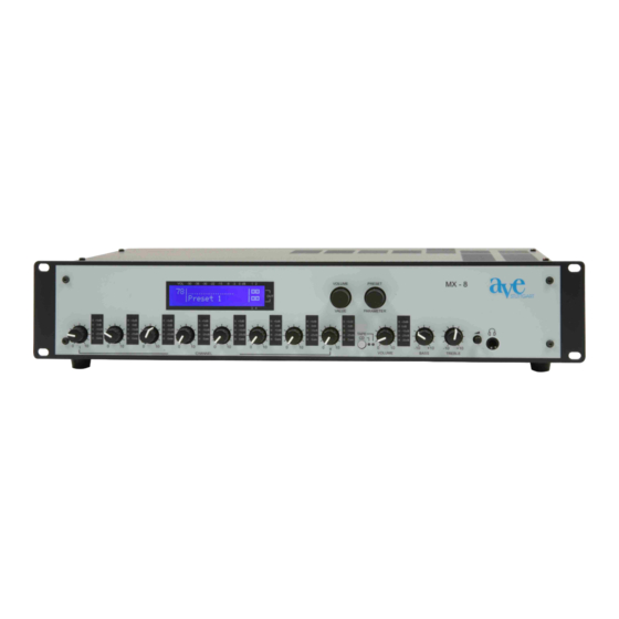
Description of front and rear panel 14 15 Front panel of the MX-8 1. Volume control (for channels 1 – 4): Allows adjustment of the level of the signal sources connected to the microphone/line inputs (26.). During installation by the technician, the optimal level will be marked on the unit. 2. -
Page 5: Basic Operation Of The Mx-8
14. Volume/Value knob: Rotary encoder with integrated pushbutton. This knob is used, among others, to set the overall volume or set other values. 15. Preset/Parameter knob: Rotary encoder with integrated pushbutton. This knob is used, among others, to switch from one preset to another. 17 18 Rear panel of the MX-8 16. -
Page 6: Changing Between Presets
enable programming for any application and make them available to the user at the touch of one’s fingertips. For each preset, the following 3 parameters are programmed: • the master volume • which of the 4 outputs are to be active •... -
Page 7: Extended Functions
well as a little square next to the corresponding number of the output. „On“ or „off“ indicate whether the output is active or not. This is also reflected in the little squares, where a dot in the middle indicates an active output. -
Page 8: Programming The Mx-8 / The Parameter Menu
• When pushing the preset knob, the 4 outputs will appear one after the other with their respective names. „On“, as well as a dot in the little square, indicate that this output is active. By turning the volume knob one click, the shown output can bei either activated or deactivated. -
Page 9: Preset
not interrupt“). Pushing the preset knob indicates „no“ and the display will show „Changes discarded!“. • The following 4 sections will describe the programming possiblities of the 4 menu items. For quick reference, there is a table of all programmable settings at the end (in section 4.2.5). -
Page 10: Config
• Limiter: Can be indivudually set for each output. By pushing the preset knob, you can chose the output; turning the volume knob by one click, you can turn the limiter either „on“ or „off“. • By pushing the volume knob you return back to the parameter menu. In case you have canged any parameters, you will be asked whether you would like to save them. -
Page 11: Quick Reference: Table With All Programmable Parameters
4.2.5 Quick reference: Table with all programmable parameters Where is which parameter set? The following table lists the parameter menu with its items and parameters: Item Parameter Description Preset Preset name Name of the preset Preset master volume Master volume of the preset Preset output Choice of active outputs Parameters... -
Page 12: Automatic Threshold Reduction, Transmission Matrix
Their functions are indicated on the label. In order to realise the function on the left, short the respective jumper. • High-pass filters for each of the 4 microphone/line inputs, 40 Hz/ 100 Hz. For the use of microphones, the jumpers should be set to 100 Hz. This high-pass (low-cut) filter reduces low-frequency vibrations and compensates for the so-called proximity effect (the booming sound often associated with close pick-up). -
Page 13: 3-Band Equalizer, Compressor/Limiter, Gain, Threshold
• Selection for each of the four inputs to which outputs (OUT 1 through OUT 4) they are to be transmitted. By default, each of the inputs are set to all four outputs. 4.3.3 3-band equalizer, compressor/limiter, gain, threshold The six potentiometers for each channel have the following functions 1. -
Page 14: Specifications
Switch 1 Hold time 256 ms 512 ms Switch 2 Active channel Last channel Channel 1 Switch 3 Switch 4 Active channels None Channel 3+4 5 Specifications DSP structure • 4 channels with completely independent 24 bit / 96 kHz digital audio processing output levels Output level and master volume •... - Page 15 Limiter • Can be enabled separately for each channel, reliably protects the sound system from sudden, unexpected increases in signal level that can lead to amplifier clipping or loud- speaker damage Preset (set of programmable parameters) • Available number of presets: 20 •...
- Page 16 • Output impedance REC: 70 Ω unsymmetrisch • Output level REC: 0 dBu Linking multiple mixers: • Impedace Link IN: 10 kΩ unbalanced • Input sensitivity: -6 dBu • Output impedance Link OUT: 100 Ω unbalanced • Output sensitivity: -6 dBu Headphones •...
Need help?
Do you have a question about the MX 8 and is the answer not in the manual?
Questions and answers