Table of Contents
Advertisement
Advertisement
Table of Contents

Related Manuals for LOTOS CT520D


Summary of Contents for LOTOS CT520D
- Page 1 LOTOS TECHNOLOGY Plasma Cutter TIG Stick Welder CT520D www.uwelding.com ®...
-
Page 2: Quick Setup
For either 110 or 220VAC, the GREEN wire is the ground wire. The WHITE and BLACK wires are hot wires. For Plasma Cutting: 1. Wear a Lotos auto darkening plasma cutting helmet (Figure 1.1, not included in the box. To purchase, please go to our website.) to protect your eyes from harmful plasma cutting arc radiation and safety gloves to protect your hands during welding. - Page 3 5. Change your consumables (tip, electrode, ring, and cup) if they are worn out. The consumables’ type is LCON. If you want to cut the perfect circle or perfect straight line, order a Lotos LCK roller guider compass kits from our website www.uwelding.com.
- Page 4 Figure 1.5 Figure 1.6 Argon a) If you switch from plasma cutting to TIG welding quite often, consider buying a LOTOS 3 way valve kit to connect both the argon tank (Figure 1.7) and the air Machine compressor simultaneously. Compressor Figure 1.7...
- Page 5 Plug Figure 1.9 3. TIG torch head parts (Figure 1.10) and assembly (Figure 1.11) (The tungsten is not included in the picture; please buy proper DC Lotos tungsten electrodes.) Grind and sharpen the tungsten before first use. Figure 1.10 Figure 1.11...
- Page 6 Last but not least, please be sure to turn off the machine when you switch from one function to another. This is important, because otherwise the machine could be damaged. All accessories and consumables can be purchased at www.uwelding.com or Lotos’s authorized resellers.
- Page 7 LOTOS Plasma Cutters User Manual Version: 2.0, May 2014 copyright @ Lotos Technology www.uwelding.com is operated by Lotos Technology ®...
-
Page 8: Table Of Contents
Table of Contents Introduction Overview ................Audience . -
Page 9: Introduction
Introduction Overview Dear Valued Customer: Thank you for purchasing a Lotos Technology plasma cutter! Feel free to check out our other products at www.uwelding.com. This User Manual documents policies and procedures for proper operation of the equipment. IMPORTANT: Be sure to review the contents of this manual before attempting to operate the equipment. -
Page 10: Safety Precautions
Safety Precautions - Read Before Using Overview Protect yourself and others from injury — read and follow these precautions. Caution Recommendations • Connect the machine to a UL-approved outlet only. Do not hard wire the machine directly to CAUTION: Welding and arc cutting the power source. -
Page 11: Fire Or Explosion
• Keep cylinders away from any welding or other falling or tipping. electrical circuits. If you encounter any difficulties during set up or operation: • Consult this manual. • Contact Lotos Customer Service by visiting http://www.uwelding.com/about-us/contact-us/. ®... -
Page 12: Equipment
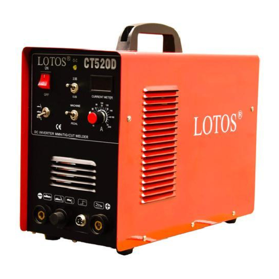
The CT520D multipurpose unit offers a variety of welding and cutting aspects. It is able to cut all types of metal up to 1/2’’ with the 50A plasma cutting function. This LOTOS multi-process welder can switch between AC/DC TIG Weld and AC/DC STICK Weld quickly and easily. - Page 13 Specifications 120-220 V, 1-PH, 27 A Rated input power requirement +/- 15%, 50/60 Hz 10-50 A @220V Output current 10-25 A @110V Plasma 60% @ 50 A Cutting Duty cycle @ 40°C (104°F) 100% @ 40 A Gas supply Clean, dry, oil-free air Recommended gas inlet 3.6 scfm @ 65 psi flow rate / pressure...
- Page 14 Torch Type Torch Type Model Amperage Consumables Type LCON0120 5 prong LCON LCON0140 CL0105 Cutting Torch LCON0190 LCON0220 Extended 5 prong LCON0240 LCON cutting CL0205 LCON0290 torch Consumables Package Part Number Nozzle Electrode Shield Cup Swirl Ring Package Type Total Pieces LN01 x 10, LCON0120 LN01...
-
Page 15: Adjustor Diagram
Amp Display Amp Adjusting 2-step & 5-step Switch Power Switch Function Switch Machine/ Pedal Switch Figure 2.1: Adjustor Diagram 1 Connect to Problem Regulator Air Compressor Indicator (TIG) (Stick) (Cutter) Figure 2.2: Adjustor Diagram 2 Power Cord Figure 2.3: Air Regulator Configuration ®... -
Page 16: Connecting Cables To Machine
220V Round Plug Power Cord Compressor Adjust to Plasma Cut Gas & Power Output Ground Ground Clamp 5-pin Cable Plug Work Piece Figure 2.3: Cutting Plasma Cutting Diagram Torch 220V Round Plug Power Cord Argon Regulator Argon Hose Argon Tank Gas &... - Page 17 220V Round Plug Power Argon Cord Regulator Argon Argon Hose Tank Gas & Power Foot Pedal with Output 5-pin Plug Ground Clamp 5-pin Plug Work Figure 2.4: (unplugged) Piece TIG Welding with Foot Pedal Diagram TIG Torch 220V Round Plug Ground Clamp (+) Work Figure 2.6:...
-
Page 18: Installations
INSTALLATION Power Cord Plug Wiring Connect this welding & cutting equipment with a power supply of 110 or 220V AC. For the wiring, please note that: For 110VAC, - The green wire with yellow stripe is the ground wire - The red/brown wire is the hot wire - The blue/black wire is the neutral wire For 220VAC, - The green wire with yellow stripe is the ground wire... -
Page 19: Gas Regulator Installation
Function Switch 2. MMA Function - Connect the plug of the electrode holder to the “+” socket on the front panel. - Connect the plug of the ground clamp to the “-” socket on the front panel. 3. Plasma Cutting Function - Use the gas hose to connect to one of the terminals on the air regulator and connect the other terminals to the copper tub. -
Page 20: Operation
OPERATION TIG Welding Function 1) While this welding & cutting equipment is operated, the power supply indicator is on; and the built-in fan will function. 2) Switch to the TIG welding function mode. 3) Press the gas release button and modulate the volume of gas output to the required value. 4) Press the button on the welding torch, and the electromagnetic valve functions. - Page 21 Plasma Cutting Function 1) Switch to the plasma-cutting mode. 2) While this welding & cutting equipment is operated, the power supply indicator is on and the built-in fan will function. 3) Release the regulator valve, and modulate the pressure and volume of output gas. 4) Press the cutting torch button.
-
Page 22: Instruction Notes
Instruction Notes Working Environment 1. The location in which this welding & cutting equipment is installed should be free of dust, corrosive chemical gases, flammable gases or materials, and of be at no more than 80% humidity. 2. Avoid welding & cutting in the open air unless sheltered from the sun, rain, and snow. The temperature of the working environment should be maintained within -10°C to +40°C. -
Page 23: Maintenance
Troubleshooting The following trouble shooting guide is for your reference only. Lotos Technology will NOT take any liability or responsibility for any injury or damage caused in such action(s). Always turn off electrical power and air supply before performing inspection and reconnection. - Page 24 Fault Symptoms Rectification 1. The normal voltage of positive and negative pole of board VH-07 should be DC 380V. 1.1 Possible short circuit, and possible misconnection of silicon bridge with the PCB. 1.2 Possible electricity leakage of capacitors; replace them if necessary.
- Page 25 Fault Symptoms Rectification 7. Unstable current output during the 1. Possible damage of 1K resistance. Replace it if necessary. welding operation, and the potentiometer 2. The connection of this welding equipment is not available. is unavailable. 8. Excessive splash generated during 1.
Need help?
Do you have a question about the CT520D and is the answer not in the manual?
Questions and answers
Anything to adjust inside the unit when switching over from 110v to 220v?
No, the LOTOS CT520D does not require internal adjustments when switching from 110V to 220V.
This answer is automatically generated