Table of Contents
Advertisement
Advertisement
Table of Contents

Related Manuals for LOTOS MIG175


Summary of Contents for LOTOS MIG175
- Page 1 LOTOS MIG175 MIG Welder...
-
Page 2: Table Of Contents
TABLE OF CONTENTS SAFETY...…………………...……………………………………………………………4 SPECIFICATIONS…………..….………………………………………………………9 General Description………………………………………………………………..9 What’s Included……………………………………………………...……………..9 Power Supply Ratings………..…………………………………………………..10 Machine Rear.……………………………………………………………………….11 Front Control Panel………………………………………………………………….11 Side Components…………..……………………………………………………….12 INSTALLATION………………………………………………………………………13 Before Installation…………………………………………………………………13 Environmental Area…………………………………………………………………13 Wire Feeder Installation……………………………………………………………..14 Welding Wire Installation…………………………………………………………..14 How to Thread Welding Wire Through the Wire Feeder…………………………..15 Shielding Gas Installation…………………………………………………………..16 OPERATION...……………………………………………………………………….17 Welding Operations…………………………………………………………………17 Welding Steps………………………………………………………………………17... - Page 3 MIG175 MIG WELDER Save This Manual You will need the manual for safety warnings and precautions, assembly instructions, operating and maintenance procedures, parts list and diagram. Keep your invoice with this manual. Write invoice number and date of purchase on the inside of the manual. Keep the manual and invoice in a safe...
-
Page 4: Safety
SAFETY WARNINGS AND PRECAUTIONS PLEASE READ AND UNDERSTAND THE FOLLOWING SAFETY HIGHLIGHTS. BE SURE THAT ALL INSTALLATION, OPERATION, MAINTENANCE AND REPAIR PROCEDURES ARE PERFORMED ONLY BY QUALIFIED INDIVIDUALS. ARC AND TIG WELDING CAN BE HAZARDOUS. PROTECT YOURSELF AND OTHERS FROM POSSIBLE SERIOUS INJURY... - Page 5 Avoid starting unintentionally. Be sure the switch is in the off position when not in use and before plugging in. Do not carry any tool with your finger on the trigger, whether it is plugged in or not. Stay alert. Watch what you are doing. Use common sense. Do not operate any tool when tired. Check for damaged parts.
- Page 6 v ELECTRIC SHOCK can be fatal Ø The electrode and work (or ground) circuits are electrically “hot” when the machine is on. Do not touch these “hot” parts with your bare skin or wet clothing. Protective clothing should be hole free, dry and ANSI approved. Wear dry, hole-free gloves to insulate hands.
- Page 7 v ARC RAYS can burn Ø Avoid eye and body damage. Arc rays and infrared radiation can cause injury to the eyes and burn the skin. Wear ANSI approved eye and body protection. Do not allow viewing by visitors without proper eye and body protection.
- Page 8 v ELECTRICALLY POWERED EQUIPMENT can be dangerous Ø Turn off input power using the disconnect switch at the fuse box before working on the equipment. Ø Install equipment in accordance with the local codes and the manufacturer’s recommendations. Ø Ground equipment accordance with...
-
Page 9: Specifications
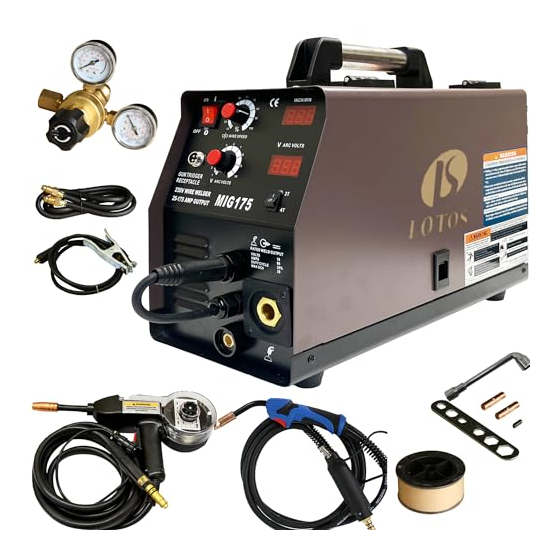
SPECIFICATIONS v GENERAL DESCRIPTION The LOTOS MIG175 is one of the most versatile welders. It is able to weld aluminum with the spool gun. Its transformer technology has been proven to be reliable and durable. MIG175 can easily connected to your existing 220V wall outlet and can be setup quickly within 10 minutes. It handles industrial standard 4”... -
Page 10: Power Supply Ratings
POWER SUPPLY RATINGS v MIG175 Output Power Input Voltages 200-240V, 1-PH, 50/60 Hz Input Current 22A @220V Power Factor 0.73 Power Efficiency 20% @175A Duty cycle @ 40°C (104°F) 30% @135A General 18” (457mm) L Specification Dimensions with handle 10.5” (267mm) W 12.5”... -
Page 11: Machine Rear
MACHINE REAR v The unit is connected to the supply even if the Power Switch is in the “OFF” position, and therefore there are electrically live parts inside the power source. Carefully follow the instructions given in this manual. REAR COMPONENTS Shielding gas inlet fitting Reset overload protective device Power cord... -
Page 12: Side Components
SIDE COMPONENTS v SIDE COMPONENTS Positive (+) and negative (-) output terminals Wing screw to fasten the welding torch cable Wire feed tension roller Wire spool mount spindle... -
Page 13: Installation
INSTALLATION PLEASE READ ENTIRE INSTALLATION SECTION BEFORE STARTING INSTALLATION. BE SURE THAT ONLY QUALIFIED PERSONNEL SHOULD PERFORM THIS INSTALLATION. __________________________________________________________________ v BEFORE INSTALLATION ELECTRIC SHOCK can be fatal w Have a qualified electrician install and service this equipment. w Turn the input power OFF and unplug the machine from the receptacle before working on this equipment. -
Page 14: Wire Feeder Installation
Reinstall by putting back the wire feed roller and tightening the Allen set screw. Ø WELDING WIRE INSTALLATION The MIG175 welding machine can be used with wire spools of either 8” (200 mm ) in diameter or 4”(100mm) in diameter. The depth of either spool should not exceed 2.2” (56 mm). -
Page 15: How To Thread Welding Wire Through The Wire Feeder
HOW TO THREAD WELDING WIRE THROUGH THE WIRE FEEDER Ø Unlock the tension bar (1) on the wire tensioner and lift up the rocker arm (2). Insure that the wire drive wheel is appropriate to the welding wire size, see above describing the installation to wire feed roller installation. -
Page 16: Shielding Gas Installation
Connect the other end of the hose to the gas inlet located at the rear of the MIG175 welding machine (The connector nipple 5/8-18 adapts to CGA-032). Ensure that the hose is not twisted or knotted. -
Page 17: Operation
Wear eye, ear and body protection. WELDING STEPS Ø 1. Plug in the MIG175 Welding Machine. 2. Straighten out the welding torch. 3. Turn ON the unit and depress the gun trigger. Feed wire and cut 1⁄4” from the end of the nozzle. -
Page 18: Welding Process
SPOOL GUN OPERATION Ø Your MIG175 can operate a hand-held spool gun. This will allow you weld both Aluminum and Steel. 1. NOTE: for use on steel 18ga - 1/4”; aluminum 1/8” plate or thicker. 2. Turn the power off and remove plug from AC outlet. -
Page 19: Overload Protection
Ø OVERLOAD PROTECTION TO WIRE FEEDER The MIG175 model has two automatic circuits to protect motor of the wire feeder, if there is fault occurred to the motor, the circuit will power off wire feeder as well as the output. -
Page 20: Welding Label
Ø WELDING LABEL... -
Page 21: Other Accessories
OTHER ACCESSORIES The following accessories and consumables can be purchased on www.uwelding.com, or call 408-739-2329 to order. CONSUMABLES MA01 ACCESSORIES...
Need help?
Do you have a question about the MIG175 and is the answer not in the manual?
Questions and answers